
Instruction Manual

Publication 1753-UM001C-EN-P - March 2010 241
Use GuardPLC Controller as an Adapter Chapter 19
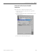
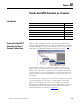
5. Configure the This Controller parameters.
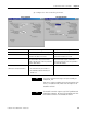
Parameter PLC-5 Controller Settings SLC 5/05 Controller Settings
Communication Command Choose PLC-5 Typed Read or PLC-5 Typed Write Choose either PLC5 Read or PLC5 Write.
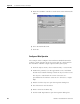
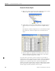
Data Table Address Enter the source file address for a write or the
destination file address for a read.
Enter the source file address for a write or the
destination file address for a read.
Size in Elements The number of items to read or write (1…1000).
The actual number of bytes transmitted is
based on the data type of the file specified in
the Data Table Address.
The number of items to read or write (1…1000).
The actual number of bytes transmitted is
based on the data type of the file specified in
the Data Table Address.
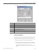
Port Number (for PLC-5 controllers)
Channel (for SLC 5/05 controllers)
Enter the Ethernet port number.
• The onboard PLC-5E port number is 2.
• The EtherNet/IP sidecar Ethernet port
number 3 A.
Enter 1 for the EtherNet/IP port.
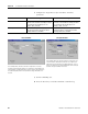
PLC-5 Controller
SLC 5/05 Controller
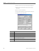
TIP
You cannot send a write message to an input assembly, for
example IN_120.
Input versus output assemblies are from the perspective of the
PLC-5 or SLC 5/05 controller, which sends the request to the
GuardPLC controller.
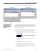
TIP
The GuardPLC controller supports only PLC-5 Typed Read and
Typed Write commands. No other PCCC commands work with
the GuardPLC controller on the EtherNet/IP network.