
Instruction Manual

Publication 1753-UM001C-EN-P - March 2010 147
Diagnostics Chapter 15
Serial Communication Indicators
1755-IB24XOB16 Module
Status Indicators
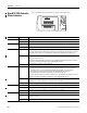
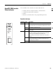
The 1755-IB24XOB16 digital combination input and output module
(AB-DIO) has status indicators for:
• power supply.
• module status.
• I/O status.
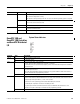
Power Supply and Module Status
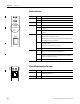
Indicator Status Description
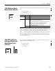
FB1 On Field bus no. 1 is active
FB2 On Field bus no. 2 is active
(serial interface module)
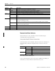
IMPORTANT
Only the bottom serial port on the GuardPLC 2000 controller is
active, as indicated by the FB2 status indicator.
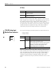
FB1
FB2
RUN
ERR
1755-
IB24XOB16
RUN
ERR
1
2
3
4
5
6
7
8
9
LS+
I1
I2
I3
I4
I5
I6
I7
I8
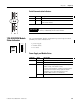
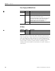
Indicator Status Description
RUN On (green) The module has the correct operating voltage (24V DC).
Off The module has no power.
ERR On (red) If the system is in Stop mode, one or more of the inputs or
outputs is faulty, or the module is faulty.
Use the RSLogix Guard PLUS! software to verify the location
of the fault. If the module is faulty, replace the module
immediately, or the safety-related operation of the
GuardPLC 2000 controller is not maintained.
Off The module is operational.