
Instruction Manual

144 Publication 1753-UM001C-EN-P - March 2010
Chapter 15 Diagnostics
Communication Status Indicators
Status indicators on the controllers and I/O modules display
communication status information.
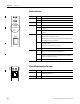
Safety-related GuardPLC Ethernet Communication
Communication via the GuardPLC Ethernet network is indicated via
two small status indicators integrated into each RJ-45 connector
socket.
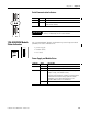
Non-safety-related Communication
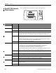
Active communication via the serial ports, COMM1 and COMM3, is
indicated by a status indicator located above the port.
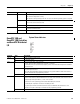
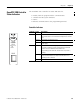
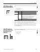
PROGress On The upload of a new controller configuration is in progress.
Flashing The upload of a new operating system into the Flash ROM is in progress.
Off No upload of controller configuration or operating system in progress.
FORCE On The controller is executing a routine (Run) and Force mode is activated by the user.
Flashing The controller is in Stop, but Forcing has been initiated and will be activated when the controller is
started.
Off Forcing is OFF.
FAULT On The routine (logic) has caused an error.
The controller configuration is faulty.
The upload of a new operating system was not successful and the operating system is corrupted.
Flashing An error has occurred during a Flash ROM write cycle.
One or more I/O errors have occurred.
Off None of the above errors has occurred.
OSL Flashing Emergency Operating System Loader is active.
BL Flashing Boot Loader unable to load operating system or unable to start COMM operating system loader.
Indicator State Description
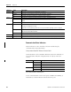
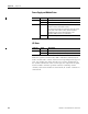
Indicator State Description
Green On Full duplex operation
Flashing Collision
Off Half duplex operation, no collision
Yellow On Connection established
Flashing Interface activity