
Instruction Manual


108 Publication 1753-UM001C-EN-P - March 2010
Chapter 12 High-Speed Counters
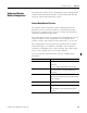
Decoder Mode
Decoder mode is used for safety supervising the inputs by Gray code,
but in the application, the bit structure is handled as a normal binary
code value. To use this value, it must be converted in the application.
The counter inputs can be connected to an incremental encoder with
4-bit binary code to recognize rotation and the direction of rotation.
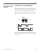
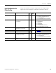
Counter Mode Inputs
Pins Functions
A1, A2 counting input for pulses (high-signals) with falling edge of the pulses
B1, B2 counting direction input, incrementing the counter with low-signal,
decrementing the counter with high-signal
Z1, Z2 resets inputs
Resets can be made with a short high-signal. A continuous high-signal
blocks the counter. Resets can also be made by the controller program.
C1, C2 has no function (GuardPLC 2000 controller - 1755-HSC only)
C- GuardPLC 2000 controller common reference pole, all pins have electrical
continuity
L- GuardPLC 1800 controller common reference pole, all pins have electrical
continuity
I- GuardPLC 1200 controller common reference pole, all pins have electrical
continuity
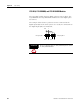
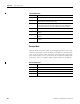
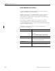
Decoder Mode Inputs
Pins Functions
A1, A2 bit 1 (LSB)
B1, B2 bit 2
Z1, Z2 bit 3
C1, C2 bit 4 (GuardPLC 2000 controllers only)