
Instruction Manual

Publication 1753-UM001C-EN-P - March 2010 105
Pulse Testing Chapter 11
Input Configuration for
Pulse Testing
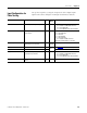
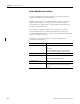
Set up these signals by using the Outputs tab of the digital inputs
Signal Connections dialogbox in RSLogix Guard PLUS! software.
Name Description Type Initial
Value
Notes
Number of Pulse Channels Number of pulse outputs being used USINT 1 to 8 1…4 for 1753-IB16
1…8 for GuardPLC 1600/2000 controllers
1…8 for 1753-IB20XOB8
1…2 for 1753-IB8XOB8 and 1753-IB16XOB8
Pulse Slot Slot occupied by the module with the
pulsed outputs
UDINT — 2 for GuardPLC 1600 controllers
2 for 1753-IB20XOB8
1 for 1753-IB16
3 for 1753-IB8XOB8
3 for 1753-IB16XOB8
1…6 for GuardPLC 2000 controllers
(wherever 1755-IB24XOB16 is located)
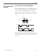
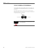
Pulse Delay Pulse delay is both the low pulse
width and pulse test duration.
UINT 400
(default)
Values in μs from 5…2000.
Error Code Error code for each switch BYTE
N/A
See Appendix
B for error code descriptions.
Value Value for each switch BOOL
DI[xx].PulseChannel Indicates which pulse output is
sourcing the input channel
USINT 1 to 8 1…4 for 1753-IB16
1…8 for GuardPLC 1600/2000 controllers
1…8 for 1753-IB20XOB8
1…2 for 1753-IB8XOB8 and 1753-IB16XOB8
DO[xx].Value Initialization value for the pulse
outputs
BOOL TRUE Each pulse output must be activated.