
Instruction Manual

Publication 1753-UM001C-EN-P - March 2010 103
Pulse Testing Chapter 11
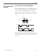
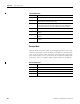
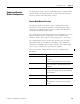
Wire for OS Configurable
Line Control
GuardPLC 1600 Controller and 1753-IB20XOB8 Module
Up to 8 digital outputs (DO1 to DO8) can be configured as pulsed
outputs. The example below shows 2 outputs, configured as pulse test
outputs, connected to the digital inputs (DI) of the same system. As a
result, the connections to the digital inputs (DI) are monitored.
The pulse outputs must begin at DO[01] and must be sequential. For
example, if two pulse outputs are required, they must be DO[01] and
DO[02].
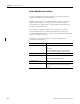
The digital outputs DO1 and DO2 are pulsed (briefly set to low) so
that the connections to the digital inputs are monitored. The duration
of the test can be configured in the range of 5…2000 μs with a default
value of 400 μs.
Emergency OFF 1 Emergency OFF 2
D
O
1 2
DI5 6
DI 7 8
DO1
DO2
Configurable 5… 2000 μs
Configurable 5…2000 μs
t