Installation Instructions GuardPLC Relay Output Module Catalog Number 1753-OW8 Topic Page Important User Information 2 About the 1753-OW8 Relay Output Module 3 General Safety 3 Install the Module 4 Mount the Module 5 Ground the Module 6 Wire the Module 6 Make Safety-related Communication Connections 8 Reset Push Button 9 Status Indicators 10 Specifications 11 Additional Resources 15
GuardPLC Relay Output Module Important User Information Solid-state equipment has operational characteristics differing from those of electromechanical equipment. Safety Guidelines for the Application, Installation and Maintenance of Solid State Controls (Publication SGI-1.1 available from your local Rockwell Automation sales office or online at http://www.rockwellautomation.com/literature/) describes some important differences between solid-state equipment and hard-wired electromechanical devices.
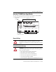
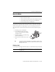
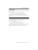
GuardPLC Relay Output Module 3 About the 1753-OW8 Relay Output Module The 1753-OW8 relay output module is a distributed I/O module for use with GuardPLC controllers. The module features eight relay outputs as shown below.
GuardPLC Relay Output Module Environment and Enclosure ATTENTION: This equipment is intended for use in a Pollution Degree 2 industrial environment, in overvoltage Category II applications (as defined in IEC publication 60664-1), at altitudes up to 2000 m (6562 ft) without derating. This equipment is considered Group 1, Class A industrial equipment according to IEC/CISPR 11.
GuardPLC Relay Output Module 5 Mount the Module IMPORTANT For effective cooling, mount the module following these guidelines. • • • • Mount the module horizontally. Provide a gap of at least 100 mm (3.94 in.) above and below the module. Select a location where air flows freely or use an additional fan. Do not mount the module over a heating device. The terminal connections meet the protection requirements according to IP20. For higher requirements, the 1753-OW8 must be mounted in an enclosure.
GuardPLC Relay Output Module Ground the Module The module is functionally grounded through its DIN rail connection. A protective earth ground connection is required and is provided through a separate grounding screw on the upper left of the housing and marked with the grounding symbol . You must also provide an acceptable grounding path for each device in your application.
GuardPLC Relay Output Module 7 Connect Safety-related Relay Outputs The module has eight relay outputs whose status is indicated via status indicators. An output is in a safety state when it is de-energized. When an internal (non-communication) fault occurs, all outputs are switched off. Each output of the module is fitted with two safety relays with positively guided contacts and one MSR-type relay. Relay outputs are connected to these terminals.
GuardPLC Relay Output Module If the 1753-OW8 module faults, all eight outputs are switched off. This is indicated by the Fault status indicator. TIP For more information on output wiring, see the GuardPLC System User Manual, publication 1753-UM001.
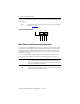
GuardPLC Relay Output Module 9 Reset Push Button The module is equipped with a reset pushbutton. Reset via the push button is necessary under the following conditions. • You forget the password to go online via the programming software. • You are unable to determine the IP address and SRS of the controller. The push button is accessible through a small round hole at the top of the housing, approximately 4…5 cm (1.6 …2.0 in.) from the left rim and recessed approximately 9.5 mm (0.375 in.).
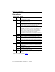
GuardPLC Relay Output Module Status Indicators Indicator Status Description 24V DC On 24V DC operating voltage present. Off No operating voltage. On This is the normal status of the module. A routine, which has been loaded into the module, is executed. The module processes input and output signals, carries out communication, and performs hardware and software tests. Flashing The module is in STOP mode and is not executing a routine. All system outputs are reset.
GuardPLC Relay Output Module 11 Specifications Technical Specifications - 1753-OW8 Attribute 1753-OW8 Interface: GuardPLC Ethernet 2 x RJ45, 10/100BaseT (with 100 Mbps) with integrated switch Operating voltage 24V DC, -15…20%, wss ≤ 15% Current consumption 0.
GuardPLC Relay Output Module Technical Specifications - 1753-OW8 Relay Outputs Number of outputs 8 normally open contacts Switching voltage ≥ 5V, ≤ 250V AC/250V DC Switching current • 24V DC @ 1 A noninductive, external fusing adapted • 250V AC @ 6 A general purpose UL: TÜV: • 30V DC, 90 W (3.15 A) max, noninductive, external fusing adapted • 70V DC, 22 W (0.315 A) max, noninductive, external fusing adapted • 127V DC, 25 W (0.25 A) max, noninductive, external fusing adapted • 250V DC, 40 W (0.
GuardPLC Relay Output Module 13 Environmental Specifications - 1753-OW8 Attribute 1753-OW8 Temperature, nonoperating -40…85 °C (-40…185 °F) • IEC 60068-2-1 (Test Ab, Unpackaged nonoperating cold) • IEC 60068-2-2 (Test Bb, Unpackaged nonoperating dry heat) • IEC 60068-2-14 (Test Na, Unpackaged nonoperating thermal shock) Temperature, operating 0…60 °C (32…140 °F) • IEC 60068-2-1 (Test Ad, operating cold) • IEC 60068-2-2 (Test Bd, operating dry heat) • IEC 60068-2-14 (Test Nb, operating thermal shock)
GuardPLC Relay Output Module Certifications Certification (when product is marked)(1) 1753-OW8 c-UL-us UL Listed Industrial Control Equipment, certified for US and Canada. See UL File E65584 CE European Union 2004/108/EC EMC Directive, compliant with: • EN 61326-1 Meas./Control/Lab., Industrial Requirements • EN 61000-6.
GuardPLC Relay Output Module 15 Additional Resources The table below provides a listing of publications that contain important information about GuardPLC systems.
Rockwell Automation Support Rockwell Automation provides technical information on the Web to assist you in using its products. At http://www.rockwellautomation.com/support/, you can find technical manuals, a knowledge base of FAQs, technical and application notes, sample code and links to software service packs, and a MySupport feature that you can customize to make the best use of these tools.