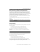
Installation Instructions GuardPLC Digital Output Module Catalog Number 1753-OB16 Topic Page Important User Information 2 About the Module 3 General Safety 3 Install the Module 4 Mount the Module 5 Ground the Module 5 Wire the Module 6 Make Connections for Safety-Related Communication 9 Reset Push Button 9 Status Indicators 10 Specifications 11 Additional Resources 14
GuardPLC Digital Output Module Important User Information Solid-state equipment has operational characteristics differing from those of electromechanical equipment. Safety Guidelines for the Application, Installation and Maintenance of Solid State Controls (Publication SGI-1.1 available from your local Rockwell Automation sales office or online at http://www.rockwellautomation.com/literature/) describes some important differences between solid-state equipment and hard-wired electromechanical devices.
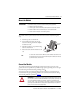
GuardPLC Digital Output Module 3 About the Module The 1753-OB16 digital output module is a 16-channel output module for use with GuardPLC controllers.
GuardPLC Digital Output Module Environment and Enclosure ATTENTION: This equipment is intended for use in a Pollution Degree 2 industrial environment, in overvoltage Category II applications (as defined in IEC publication 60664-1), at altitudes up to 2000 m (6562 ft) without derating. This equipment is considered Group 1, Class A industrial equipment according to IEC/CISPR 11.
GuardPLC Digital Output Module 5 Mount the Module IMPORTANT For effective cooling, mount the module following these guidelines. • • • • Mount the module horizontally. Provide a gap of at least 100 mm (3.94 in.) above and below the module. Select a location where air flows freely or use an additional fan. Do not mount the module over a heating device. The module cannot be panel-mounted. Mount the module to a DIN rail by following these steps. 1. Hook the top slot over the DIN rail. 2.
GuardPLC Digital Output Module Wire the Module The following sections describe how to connect the voltage supply and connect the inputs and outputs. Connect the Voltage Supply To comply with CE Low Voltage Directives (LVD) and UL restrictions, you must use either a Safety Extra Low Voltage (SELV), or a Protected Extra Low Voltage (PELV) power supply to power this module. A SELV supply cannot exceed 30V rms, 42.4V peak, or 60V DC under normal conditions and under single-fault conditions.
GuardPLC Digital Output Module 7 Safety-related Digital Outputs The module has 16 digital outputs (DO1…DO16) whose status is indicated via status indicators. An output is in a safe state when it is de-energized. If a fault occurs, all outputs are turned off. Each of the 16 outputs can have a load of 1 A at the ambient temperature of 60 °C (140 °F) or up to 2 A at a maximum temperature of 40 °C (104 °F).
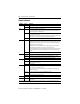
GuardPLC Digital Output Module Terminal Number Designation Function 13 L- Reference pole 14 9 Digital output DO 9 15 10 Digital output DO 10 16 11 Digital output DO 11 17 12 Digital output DO 12 18 L- Reference pole 19 L- Reference pole 20 13 Digital output DO 13 21 14 Digital output DO 14 22 15 Digital output DO 15 23 16 Digital output DO 16 24 L- Reference pole For connection of a load, the reference pole L- of the related channel group must be used (2-pole conne
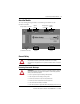
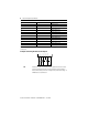
GuardPLC Digital Output Module 9 Make Connections for Safety-Related Communication The module has two 10/100BaseT, RJ45 connectors on the bottom of the unit, that provide communication to the GuardPLC controller via GuardPLC Ethernet protocol. Because this is an Ethernet switch, you can daisy-chain connections from the GuardPLC module to other distributed I/O modules. The switch is auto-detect. Either crossover or straight-through cabling can be used. Star or line configurations are available.
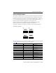
GuardPLC Digital Output Module Status Indicators Indicator State Condition 24V DC On 24V DC operating voltage present. Off No operating voltage. On This is the normal status of the controller. A routine, which has been loaded into the controller, is executed. The controller processes input and output signals, carries out communication, and performs hardware and software tests. Flashing The controller is in STOP mode and is not executing a routine. All system outputs are reset.
GuardPLC Digital Output Module 11 Specifications Technical Specifications – 1753-OB16 Module Attribute 1753-OB16 Interfaces: GuardPLC Ethernet 2 x RJ45, 10/100Base T (with 100 Mbit/s) with integrated switch Operating voltage 24V DC, -15…20%, wss 15% from a power supply with protective separation, conforming to IEC 61131-2 requirements Isolation voltage 50V (continuous), Basic Insulation Type, I/O to Ethernet and Ethernet to DC power Wiring category (1) Wire size Category 2 on communication port
GuardPLC Digital Output Module Technical Specifications – 1753-OB16 Module Current per group (admissible total current) 8 A max (16 A max) Lamp load 10 W max (for output 1 A), 25 W max (for output 2 A) Inductive load 500 mH max Internal voltage drop 2V max @ 2 A Leakage current (with 0 signal) 1 mA max @ 2V Response to overload Shut down of concerned output with cyclic reconnecting (1) Use this Conductor Category information for planning conductor routing.
GuardPLC Digital Output Module 13 Environmental Specifications – 1753-OB16 Module • ±2 kV @ 5 kHz on DC power ports • ±1 kV @ 5 kHz on signal ports • ±1 kV @ 5 kHz on communication ports • ±500V line-line (DM) and ±500V line-earth (CM) EFT/B Immunity • IEC 61000-4-4 Surge Transient Immunity • IEC 61000-4-5 on DC power ports • ±1 kV line-earth (CM) on signal ports • ±1 kV line-earth (CM) on communication ports 10V rms with 1 kHz sine-wave 80% AM from 150 kHz…80 MHz Conducted RF Immunity • IEC 61000
GuardPLC Digital Output Module Additional Resources The table below provides a listing of publications that contain important information about GuardPLC systems.
GuardPLC Digital Output Module 15 Rockwell Automation Publication 1753-IN005B-EN-P - June 2010
Rockwell Automation Support Rockwell Automation provides technical information on the Web to assist you in using its products. At http://www.rockwellautomation.com/support/, you can find technical manuals, a knowledge base of FAQs, technical and application notes, sample code and links to software service packs, and a MySupport feature that you can customize to make the best use of these tools.