
Instruction Manual

GuardPLC 1800 Controllers 9
Rockwell Automation Publication 1753-IN002C-EN-P - June 2010
LS+, not L+, should be used for short-circuit protection. Each LS+ features individual
short-circuit and EMC protection that make it important to use LS+ for only its eight related
inputs.
Line Control
The short-circuit and line break monitoring system, such as E-stop inputs, cannot be configured
for the GuardPLC 1800 controller. This is due to the fact that the 24 discrete inputs are actually
analog inputs with a resolution of one bit.
Safety-Related Analog Inputs
The controller has 8 analog inputs with transmitter supplies for the unipolar measurement of
voltages from 0…10V, referenced to L-. A 10 KΩ shunt is used for single-ended voltage signals.
With a 500 Ω shunt resistor, currents from 0…20 mA can also be measured.
The feeder lines should be no more than 300 m (984 ft) in length. Use shielded, twisted-pair
cables, with the shields connected at both ends, for each measurement input.
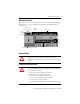
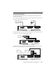
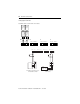
Unused analog inputs must be short-circuited. Place wire jumpers into any inputs that are not
used.
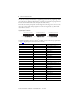
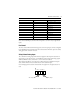
31 LS+ Sensor supply for inputs 17…24
32 17 Digital input 17
33 18 Digital input 18
34 19 Digital input 19
35 20 Digital input 20
36 21 Digital input 21
37 22 Digital input 22
38 23 Digital input 23
39 24 Digital input 24
40 L- Reference pole
Terminal Number Designation Function
AI
T1 I1 L- T2 I2 L-
41 42 43 44 45 46
Wire Jumper
Wire Jumper