
Instruction Manual

22 GuardPLC 1800 Controllers
Rockwell Automation Publication 1753-IN002C-EN-P - June 2010
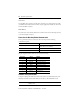
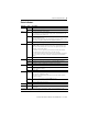
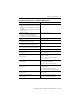
Counters
Number of counters 2 (not electrically isolated)
Inputs 3 per counter (A, B, Z)
Input voltages 5V and 24V DC
High signal (5V DC): 4…6V
High signal (24V DC): 13…33V
Low signal (5V DC): 0…0.5V
Low signal (24V DC): -3…5V
Input currents 1.4 mA @ 5V DC
6.5 mA @ 24V DC
Input impedance 3.7 kΩ
Counter resolution 24-bit
Input frequency, max 100 kHz
Triggered on negative edge
Edge steepness 1 V/μs
Pulse duty factor 1:1
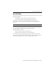
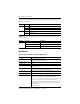
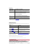
Analog Inputs
Number of inputs 8 (unipolar, not electrically isolated)
External shunt
(for current measurement)
500 Ω for 0…20 mA
Input values related to L- Nominal Value: 0…10V DC or 0…20 mA with 500 Ω shunt
Service Value: -0.1…11.5V DC or -0.4…23 mA with 500 Ω shunt
Input impedance 1 MΩ
Internal resistance of the
signal source
≤ 500 Ω
Overvoltage protection +15V, -4V
Resolution (A/D converter) 12-bit
Accuracy 0.1% @ 25 °C (77 °F)
0.5% @ 60 °C (140 °F)
Transmitter supplies 25.37…28.24V / ≤ 46 mA, short-circuit proof
Safety accuracy ± 2%
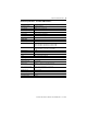
(1) Use this Conductor Category information for planning conductor routing. Refer to Industrial Automation Wiring and
Grounding Guidelines, publication 1770-4.1
.
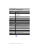
Technical Specifications – GuardPLC 1800 Controllers