
Instruction Manual

GuardPLC 1800 Controllers 15
Rockwell Automation Publication 1753-IN002C-EN-P - June 2010
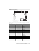
High-speed Counter Terminals
Terminals accommodate wires up to 1.5 mm
2
(16 AWG). Counters are connected to these
terminals.
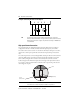
Make Communication Connections
The controller supports separate connections for safety and nonsafety-related communication.
Connections for Safety-related Communication
The controller has four 10/100BaseT, RJ45 connectors to provide communication via
GuardPLC Ethernet protocol to distributed I/O and other GuardPLC controllers, OLE for
Process Control (OPC) servers, and with the programming software. Connectors 1 and 2 are on
the bottom side on the left. Connectors 3 and 4 are on the top side on the left. All four
connectors and the GuardPLC processor are connected together by an internal Ethernet switch.
The switches are auto-detect. Either crossover or straight-through Ethernet cabling can be used.
Star or line configurations are available. Make sure that a network loop is not generated. Data
packets must be able to reach a node only via a single path.
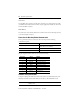
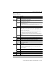
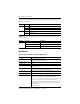
Terminal Number Designation Counter Function Gray Code Function
65 A1 Input A1 bit 0 (LSB)
66 B1 Input B1 bit 1
67 Z1 Input Z1 bit 2 (MSB)
68 L- Common reference pole
69 A2 Input A2 bit 0 (LSB)
70 B2 Input B2 bit 1
71 Z2 Input Z2 bit 2 (MSB)
72 L- Common reference pole
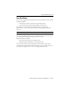
IMPORTANT
D
Do not terminate unused inputs.
TIP
For more information on GuardPLC system wiring and counter
configuration, see the GuardPLC Controller Systems User Manual,
publication 1753-UM001.
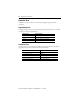
HSC
A1 B1 Z1 L- A2 B2 Z2 L-
65 66 67 68 71 7269 70