
Owner's manual
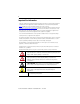
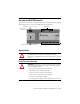
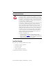
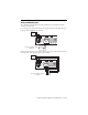
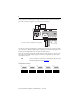
Table Of Contents
8
Rockwell Automation Publication 1753-IN001C-EN-P - June 2010
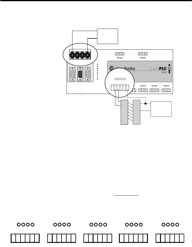
Devices with their own dedicated power supply can also be connected. Connect the reference
pole of the external power supply to the L- reference pole of the input.
The safe state of an input is indicated by a 0 signal being passed to the user program logic. If the
test routines detect a fault in the digital inputs, a 0 signal is processed in the user program for the
defective channel. When a fault occurs, the inputs are switched off (0).
Follow the closed-circuit principle for external wiring when connecting sensors. To create a safe
state in the event of a fault, the input signals revert to the de-energized state (0). The FAULT
status indicator activates.
Digital Input Terminals
TIP
For more information on input wiring, see the GuardPLC Controller Systems
User Manual, publication number 1753-UM001.
123456
1234
1L-
L-L- L+ L+
L-DO 2
(2A)
34
1LS+- LS+ LS+ LS+ LS+L-
D1
234
56
13 14 15 16 17 18
5L-
D1
678
19 20 21 22 23 24
9L-
D1
10 11 12
25 26 27 28 29 30
13 L-
D1
14 15 16
31 32 33 34 35 36
17 L-
D1
18 19 20
37 38 39 40 41 42
19 20 21 22 23 2413 14 15 16 23 24 25 26 27 28 29 30 31 32 33 34 35 36 37 38 39 40 41 42
789101112
78910
5L- L-DO 6
(2A)
7 8
11 12
COMM1
MODBUS
RS-485
24V DC
COMM2 COMM3
RUN
24 V DC
GuardPLC Ethernet
10/100 BaseT
PROG
ERROR
FAULT
FORCE
BL
OSL
PROFIBUS
3
(—)
4
(—)
3
(—)
4
(—)
1753-L28BBBM
20 DC Inputs
8 DC Outputs
1LS+- L-
D1
234
13 14 15 16 17 18
13 14 15 16 23 24
L-L- L+ L+
24V DC
24V DC
Power
Supply
COMCOM
+
24V DC
Power
Supply
COM
+
+
Light Curtain
(or any Safety Input)
Connection of Devices with Dedicated Power Supplies
1LS+- LS+LS+LS+LS+L-
DI
234
13 14 15 16 17 18
5L-
DI
678
19 20 21 22 23 24
9L-
DI
10 11 12
25 26 27 28 29 30
13 L-
DI
14 15 16
31 32 33 34 35 36
17 L-
DI
18 19 20
37 38 39 40 41 42
19 20 21 22 23 2413 14 15 16 17 18 25 26 27 28 29 30 31 32 33 34 35 36 37 38 39 40 41 42