
Owner's manual
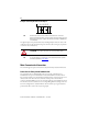
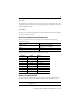
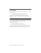
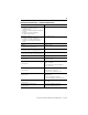
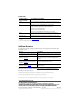
Table Of Contents
17
Rockwell Automation Publication 1753-IN001C-EN-P - June 2010
Communication via GuardPLC Ethernet protocol is indicated by two small status indicators
integrated into all connecting sockets.
Additional nonsafety-related communication occurs on the field buses and is indicated by these
status indicators.
Specifications
Indicator State Description
Green On Full-duplex operation
Flashing Collision
Off Half-duplex operation, no collision
Yellow On Connection established
Flashing Interface activity
Indicator Connection Description
Green COMM 1 RS-485 interface, field bus active
COMM 2 Unassigned
COMM 3 Unassigned
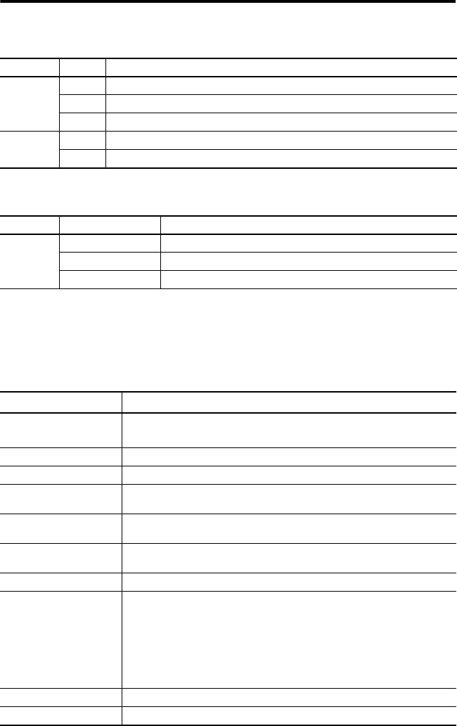
Technical Specifications – GuardPLC 1600 Controllers
Attribute 1753-L28BBB-M, 1753-L28BBB-P
User Memory 250 KB max user program memory
250 KB max application data memory
Watchdog, min 10 ms
Safety time, min 20 ms
Current consumption 8 A max (with max load)
0.5 A idle current
Operating voltage 24V DC, -15% to 20%, w
ss
≤ 15% (from a power supply with protective
separation conforming to IEC 61131-2 requirements)
Isolation voltage 50V (continuous), Basic Insulation Type, I/O to Ethernet and Ethernet to DC
power
Wiring category
(1)
Category 2 on communication ports, signal ports, and power ports
Wire size • I/O – 0.13…1.3 mm
2
(26…16 AWG) solid or stranded copper wire rated at
75 °C (167 °F) or greater with 1.2 mm (3/64 in.) insulation max
• Power – 0.33…2.1 mm
2
(22…14 AWG) solid or stranded copper wire rated
at 75 °C (167 °F) or greater with 1.2 mm (3/64 in.) insulation max
• Ethernet – RJ45 connector according to IEC 60603-7, 2-pair or 4-pair
Category 5e minimum cable according to TIA 568-B.1, or Category 5 cable
according to ISO/IEC 24702
• Comm: 9-pin D-sub
Wire type Shielded on Ethernet
Terminal block torque 0.51 N•m (4.5 lb•in)