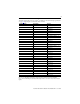
Installation Instructions GuardPLC 1600 Controllers Catalog Numbers 1753-L28BBB-M, 1753-L28BBB-P Topic Page Important User Information 2 About the GuardPLC 1600 Controller 3 General Safety 3 Install the Controller 4 Mount the Controller 5 Ground the Controller 5 Wire the Controller 6 Make Communication Connections 12 Reset Push Button 14 Controller Tests 15 Status Indicators 16 Specifications 17 Additional Resources 20
Important User Information Solid-state equipment has operational characteristics differing from those of electromechanical equipment. Safety Guidelines for the Application, Installation and Maintenance of Solid State Controls (Publication SGI-1.1 available from your local Rockwell Automation sales office or online at http://www.rockwellautomation.com/literature/) describes some important differences between solid-state equipment and hard-wired electromechanical devices.
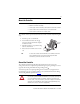
About the GuardPLC 1600 Controller The GuardPLC 1600 controller is a programmable electronic system featuring 20 digital inputs, 8 digital outputs, and 4 connections for GuardPLC Ethernet communication.
Environment and Enclosure ATTENTION: This equipment is intended for use in a Pollution Degree 2 industrial environment, in overvoltage Category II applications (as defined in IEC publication 60664-1), at altitudes up to 2000 m (6562 ft) without derating. This equipment is considered Group 1, Class A industrial equipment according to IEC/CISPR 11.
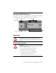
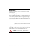
Mount the Controller IMPORTANT For effective cooling, mount the controller following these guidelines. • • • • Mount the controller horizontally. Provide a gap of at least 100 mm (3.94 in.) above and below the controller. Select a location where air flows freely or use an additional fan. Do not mount the controller over a heating device. The controller cannot be panel-mounted. Mount the controller to a DIN rail by following these steps. 1. Hook the top slot over the DIN rail. 2.
Wire the Controller The following sections describe how to connect the voltage supply and wire the controller’s digital inputs and outputs. Connect the Voltage Supply The 24V DC voltage supply must feature galvanic isolation (in accordance with EN 60950 or UL 1950) since inputs and outputs are not electrically isolated from the processor.
Safety-related Digital Inputs The controller has 20 digital inputs whose status is indicated via status indicators when the controller is in RUN mode. LS+ is a voltage source that provides 24V DC for a group of four dry contact inputs. There are five groups on the GuardPLC 1600 controller.
Devices with their own dedicated power supply can also be connected. Connect the reference pole of the external power supply to the L- reference pole of the input.
Terminals accommodate wires up to 1.5 mm2 (16 AWG). See the terminal torque specifications on page 17. Digital inputs are connected to these terminals.
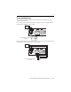
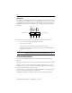
Line Control Line control is a short-circuit and line-break monitoring system (that is, E-stop inputs) that can be configured for the GuardPLC 1600 system. Up to eight digital outputs (DO1…DO8) can be configured as pulsed outputs. The example below shows two pulse outputs connected to the digital inputs (DI) of the same system. As a result, the connections to the digital inputs (DI) are monitored.
Digital Output Terminals 1 2 3 4 5 6 7 8 9 10 11 12 1 2 3 4 5 6 7 8 9 10 11 12 DO L- 1 2 3 4 L(2A) DO L- 5 6 7 8 L(2A) Terminals accommodate wires up to 1.5 mm2 (16 AWG). See the terminal torque specifications on page 17. Digital outputs are connected to these terminals. Terminal Number Designation Function Current 1 L- Reference pole — 2 1 Digital output 1 0.5 A 3 2 Digital output 2 0.5 A 4 3 Digital output 3 0.5 A 5 4 Digital output 4 (for increased load) 2.
TIP L- DO 4 DO 3 DO 2 DO 1 L- Example: Connecting Actuators to the Outputs Inductive loads can be connected without a protection diode on the load. However, Rockwell Automation strongly recommends that a protection diode be fitted directly to the load to suppress any interference voltage. A 1N4004 diode is recommended. The digital outputs can be pulsed with the safety-related digital inputs of the same device.
OPC Server The GuardPLC 1600 controller is an OPC client. An OPC server, catalog number 1753-OPC, is available from Rockwell Automation and lets computer applications read and write data to and from the GuardPLC controller. MAC Address The media access control (MAC) address of the controller can be found on the label positioned over both lower RJ45 connections.
Reset Push Button The controller is equipped with a reset push button. Reset via the push button is necessary under the following conditions. • You forget the password to go online via the programming software. • You are unable to determine the IP address and SRS of the controller. The push button is accessible through a small round hole at the top of the housing, approximately 4…5 cm (1.6…2.0 in.) from the left rim and recessed approximately 9.5 mm (0.375 in.).
Controller Tests In addition to the tests for safety, the controller tests the supply voltage and controller temperature. Supply Voltage Tests The supply voltage (24V DC) is monitored and the alarm and system shutdown are controlled according to the voltage levels listed below. Voltage Level System Condition 19.3…28.8V Normal < 19.3V Alarm state 1 (internal variables are written) < 15.4V Alarm state 2 (prepares for shutdown) < 13.
Status Indicators Indicator State Description 24V DC On 24V DC operating voltage present. Off No operating voltage. On This is the normal status of the controller. A routine, which has been loaded into the controller, is executed. The controller processes input and output signals, carries out communication, and performs hardware and software tests. Flashing The controller is in STOP mode and is not executing a routine. All system outputs are reset.
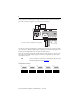
Communication via GuardPLC Ethernet protocol is indicated by two small status indicators integrated into all connecting sockets. Indicator Green Yellow State Description On Full-duplex operation Flashing Collision Off Half-duplex operation, no collision On Connection established Flashing Interface activity Additional nonsafety-related communication occurs on the field buses and is indicated by these status indicators.
Technical Specifications – GuardPLC 1600 Controllers Attribute 1753-L28BBB-M, 1753-L28BBB-P Fuse (external) 24V DC power: 10 A (time-lag) Enclosure type rating Meets IP20 Width, approx. 257 mm (10.1 in.) Height, approx. 114 mm (4.49 in.) including latch Depth, approx. 66 mm (2.60 in.) including grounding bolt Weight 1.2 kg (2.64 lb) Digital Inputs Number of inputs On-state 20 (not electrically isolated) Voltage: 15…30V DC Current consumption: ≥ 2 mA @ 15V 7.
Environmental Specifications – GuardPLC 1600 Controllers Attribute 1753-L28BBB-M, 1753-L28BBB-P Temperature, nonoperating -40…85 °C (-40…185 °F) • IEC 60068-2-1 (Test Ab, Unpackaged nonoperating cold) • IEC 60068-2-2 (Test Bb, Unpackaged nonoperating dry heat) • IEC 60068-2-14 (Test Na, Unpackaged nonoperating thermal shock) Temperature, operating 0…60 °C (32…140 °F) • IEC 60068-2-1 (Test Ad, operating cold) • IEC 60068-2-2 (Test Bd, operating dry heat) • IEC 60068-2-14 (Test Nb, operating thermal
Certifications Certification (when product is marked)(1) 1753-L28BBB-M, 1753-L28BBB-P c-UL-us UL Listed Industrial Control Equipment, certified for US and Canada. See UL File E65584. CE European Union 2004/108/EC EMC Directive, compliant with: • EN 61326-1 Meas./Control/Lab., Industrial Requirements • EN 61000-6.