Installation Instructions GuardPLC 1753-IF8XOF4 Analog I/O Module Catalog Number 1753-IF8XOF4 Inside ................................................................................................page Related Documentation ............................................................................3 Description ................................................................................................4 General Safety ..................................................................................
GuardPLC 1753-IF8XOF4 Analog I/O Module Important User Information Solid state equipment has operational characteristics differing from those of electromechanical equipment. Safety Guidelines for the Application, Installation and Maintenance of Solid State Controls (Publication SGI-1.1 available from your local Rockwell Automation sales office or online at http://www.ab.com/manuals/gi) describes some important differences between solid state equipment and hard-wired electromechanical devices.
GuardPLC 1753-IF8XOF4 Analog I/O Module 3 Related Documentation The table below provides a listing of publications that contain important information about GuardPLC Controller systems. For Read this document Publication number Detailed information regarding the safety certification of the GuardPLC System. GuardPLC Controller Systems Safety Reference Manual 1753-RM002 Detailed information on installing, wiring, configuring, operating, maintaining, and troubleshooting GuardPLC systems.
GuardPLC 1753-IF8XOF4 Analog I/O Module Description The 1753-IF8XOF4 module is a distributed safety I/O module for use with GuardPLC controllers. The module features 8 safety analog inputs and 4 standard analog outputs. The module communicates with the GuardPLC controller via GuardPLC Ethernet.
GuardPLC 1753-IF8XOF4 Analog I/O Module 5 Open style devices must be provided with environmental and safety protection by proper mounting in enclosures designed for specific application conditions. ATTENTION Environment and Enclosure This equipment is intended for use in a Pollution Degree 2 industrial environment, in overvoltage Category II applications (as defined in IEC publication 60664-1), at altitudes up to 2000 meters without derating.
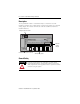
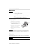
GuardPLC 1753-IF8XOF4 Analog I/O Module Mount the Module IMPORTANT For effective cooling: • Mount the module horizontally. • Provide a gap of at least 100 mm (3.94 in.) above and below the module. • Select a location where air flows freely or use an additional fan. • Do not mount the module over a heating device. The module cannot be panel-mounted. Mount the module to a DIN rail by following the steps below. 1. Hook the top slot over the DIN rail. 2.
GuardPLC 1753-IF8XOF4 Analog I/O Module 7 Wire the Module Ground the Module You must provide an acceptable grounding path for each device in your application. For more information on proper grounding guidelines, refer to the Industrial Automation Wiring and Grounding Guidelines, publication number 1770-4.1. The I/O module is functionally grounded through its DIN rail connection.
GuardPLC 1753-IF8XOF4 Analog I/O Module Connect the Voltage Supply The 24V dc voltage supply must feature galvanic isolation (in accordance with EN 60950 or UL 1950) since inputs and outputs are not electrically isolated from the internal processor. In order to comply with CE Low Voltage Directives (LVD), you must use either a NEC Class 2, a Safety Extra Low Voltage (SELV) or a Protected Extra Low Voltage (PELV) power supply to power this module. A SELV supply cannot exceed 30V rms, 42.
GuardPLC 1753-IF8XOF4 Analog I/O Module 9 Analog cabling should be no more than 300 m (984 ft) in length and must be shielded, twisted-pair cables for each measurement input. The shields must be connected at one end. IMPORTANT Short-circuit unused input channels to the reference pole by connecting wire jumpers.
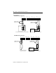
GuardPLC 1753-IF8XOF4 Analog I/O Module Wiring Examples 1753-IF8XOF4 with a 4-wire device: AI T1 I1 L- T2 I2 L- AI T3 I3 L- T4 I4 L- AI T5 I5 L- T6 I6 L- AI T7 I7 L- T8 I8 L- 1 2 3 4 5 6 7 8 9 10 11 12 13 14 15 16 17 18 19 20 21 22 23 24 10 KΩ for Voltage 500 Ω for Current 10 KΩ for Voltage 500 Ω for Current + + + 24V dc + Power Supply COM + 4-wire Device with Power Source from GuardPLC 4-wire Device with External Power Source 1753-IF8XOF4 with a 2-wire device: AI T1 I1 L- T2 I2 L- AI T3
GuardPLC 1753-IF8XOF4 Analog I/O Module 11 Analog Input Terminals Analog inputs (AI) are connected to the following terminals: Terminal Number Designation Function 1 T1 Sensor supply 1 2 I1 Analog input 1 3 L- Reference pole input 1 4 T2 Sensor supply 2 5 I2 Analog input 2 6 L- Reference pole input 2 7 T3 Sensor supply 3 8 I3 Analog input 3 9 L- Reference pole input 3 10 T4 Sensor supply 4 11 I4 Analog input 4 12 L- Reference pole input 4 13 T5 Sensor supply 5 14
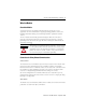
GuardPLC 1753-IF8XOF4 Analog I/O Module Position the clip over the uninsulated cable shielding and push it into the slots of the shield contact plate until it fits firmly in place, as shown below. 41 42 43 44 45 51 52 mesh shielded cable IMPORTANT cable clip Make sure that the mesh comes in direct contact with the shield contact plate. If the mesh does not touch the plate, the cable is not grounded. Standard Analog Outputs The module has 4 analog outputs, which are not safety-rated outputs.
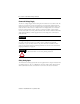
GuardPLC 1753-IF8XOF4 Analog I/O Module 13 + current output voltage output Wiring Example - + - 500 Ω Ground cable shields at the shield plate.
GuardPLC 1753-IF8XOF4 Analog I/O Module Reset Pushbutton You can use the reset button if you forget the password for connecting the programming software. The pushbutton is accessible through a small round hole at the top of the housing, approximately 4 to 5 cm (1.6 to 2.0 in.) from the left rim and recessed approximately 9.5 mm (0.375 in.). IMPORTANT Activate the reset pushbutton using an insulated pin to prevent short-circuits.
GuardPLC 1753-IF8XOF4 Analog I/O Module 15 Troubleshoot with LED Indicators Indicator State Condition 24V dc On 24V dc operating voltage present. Off No operating voltage. On This is the normal status of the module. A routine, which has been loaded into the controller, is executed. The controller processes input and output signals, carries out communication, and performs hardware and software tests. Flashing The controller is in STOP mode and is not executing a routine.
GuardPLC 1753-IF8XOF4 Analog I/O Module Indicator State Condition OSL Flashing Emergency Operating System Loader is active. BL Flashing Boot Loader unable to load operating system or unable to start COMM operating system loader. Controller status can be interrogated through the programming software. For more information, refer to the GuardPLC™ Controller Systems User Manual (1753-UM001).
GuardPLC 1753-IF8XOF4 Analog I/O Module 17 Analog Inputs Number of Inputs 8 (not electrically isolated) Input Signal Range, Nominal Voltage: 0 to +10V dc Current: 0 to +20 mA(3) Input Signal Range, Service Voltage: -0.1 to +11V dc Current: -0.4 to +23 mA(3) Shunt Resistor, External 500 Ω (for current input) Impedance, Analog Input >2 MΩ Analog Input Signal, Source Impedance ≤ 500 Ω Input Resolution 12 bits Effective Resolution 9 bits @ 10V Sensor Supply selectable 26V/8.
GuardPLC 1753-IF8XOF4 Analog I/O Module Environmental Conditions Storage Temperature IEC 60068-2-1 (Test Ab, Un-packaged Non-operating Cold), IEC 60068-2-2 (Test Bb, Un-packaged Non-operating Dry Heat), IEC 60068-2-14 (Test Na, Un-packaged Non-operating Thermal Shock): -40°C to +85°C (-40°F to +185°F) without backup battery Operating Temperature IEC 60068-2-1 (Test Ad, Operating Cold), IEC 60068-2-2 (Test Bd, Operating Dry Heat), IEC 60068-2-14 (Test Nb, Operating Thermal Shock): 0°C to +60°C (+32°F
GuardPLC 1753-IF8XOF4 Analog I/O Module 19 Certifications (when product is marked)(2) c-UL-us UL Listed Industrial Control Equipment, certified for US and Canada CE European Union 89/336/EEC EMC Directive, compliant with: • EN 61000-6-4; Industrial Emissions • EN 61000-6-2; Industrial Immunity C-Tick Australian Radiocommunications Act, compliant with: AS/NZS CISPR 11; Industrial Emissions TÜV TÜV Certified for Functional Safety (1) Use this Conductor Category information for planning conductor ro
GuardPLC is a trademark of Rockwell Automation, Inc. All other trademarks are the property of their respective holders and are hereby acknowledged. Publication 1753-IN013A-EN-P - September 2005 PN 40071-201-01(1) Copyright © 2005 Rockwell Automation, Inc. All rights reserved. Printed in the U.S.A.