
Installation Instructions User guide

GuardPLC 8-Digital Inputs and 8-Digital Outputs Module 9
Publication 1753-IN010A-EN-P - October 2005
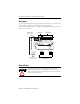
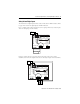
Safety-Related Digital Inputs
The module has 8 digital inputs whose status is indicated via LED indicators. Refer
to page 4 for location of digital inputs and LED indicators.
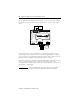
LS+ is a voltage source that provides 24V dc for a group of four dry contact inputs.
There are two groups on the module.
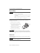
If devices require 24V dc to operate and use the same power source as the
GuardPLC, then wire the outputs of the device directly to inputs on the GuardPLC.
PO PULSE TEST
L-L- L+ L+
1LS+ LS+L-234 5L-
DID1
678
19 20 21 22 23 24
1L- L-234+
789101112
25 26 27 28 29 30
24V DC
RUN
24 V DC
PROG
ERROR
FAULT
FORCE
BL
OSL
GuardPLC Ethernet
10/100 BaseT
1
()
2
()
1753-IB8XOB8
8 DC Inputs
8 DC Outputs
5L- L-678+
13 14 15 16 17 18
1L- S+24-8-
123456
DO- DO (2A) (2A)DO
L-L- L+ L+
24V DC
24V dc
Power
Supply
COM
+
19 20 21 22 23 24
1LS+- L-
DI
234
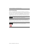
COM
+
Light Curtain
(or any Safety Input Device)