
Installation Instructions User guide

GuardPLC 8-Digital Inputs and 8-Digital Outputs Module 15
Publication 1753-IN010A-EN-P - October 2005
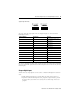
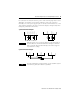
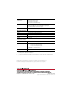
For connection of a load, the reference pole L- of the channel group must be used.
Although L- at terminals 7 and 12 and at terminals 13 and 18 are connected
internally to L- on the power supply input, it is strictly recommended to use 7 and
12 for outputs 1 through 4 only and 13 and 18 for outputs 5 through 8 only. EMC
testing was performed in this manner.
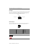
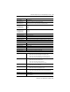
1-pole Connection Examples
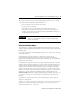
2-pole Connection Example
TIP
Inductive loads can be connected without a protection diode on
the load. However, Rockwell Automation strongly recommends
that a protection diode be fitted directly to the load to suppress
any interference voltage.
TIP
For more information on output wiring, see the GuardPLC System
User Manual, publication number 1753-UM001.
DO 1
DO 2
DO 3
DO 4
L-
L-
S+
DO 4-
DO 8-
DO4-
DO8-
DO4
DO8