
Installation Instructions User guide

GuardPLC 8-Digital Inputs and 8-Digital Outputs Module 13
Publication 1753-IN010A-EN-P - October 2005
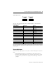
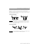
When line control detects any of the following faults, inputs are set to 0, a fault
code is generated, and the FAULT LED indicator is on.
• short-circuit between two parallel connections
• reversal of two connections
• earth fault on one of the lines (only with earthed reference pole)
• line break or opening of the contacts (e.g., when one of the E-stop off
switches is pressed in the example above), the FAULT LED indicator is on
and the fault code is generated.
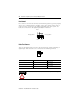
Safety-Related Digital Outputs
The module has 8 positive-switching digital outputs that switch 24V dc and two
negative-switching digital outputs that switch 24V com whose status is indicated via
LED indicators.
The positive and negative-switching digital outputs can be connected in a one-pole
or two-pole manner.
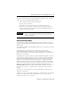
If configured for one-pole operation, use the reference pole L- for the
positive-switching outputs and reference pole S+ for the negative-switching
outputs. The total output current of the module is limited to 8 A and is generated
from the 24V of the system.
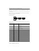
If configured for two-pole operation, the positive-switching output DO4 operates
with the negative-switching output DO4- and the positive-switching output DO8
operates with the negative-switching output DO8-. Line control is carried out for
detection of an external short-circuit between positive and negative-switching
outputs. A switch-on delay is necessary for inductive or capacitive load or lamp
load since the inrush of these loads may be mistakenly detected as a short-circuit.
This delay is set in the RSLogix Guard PLUS! Hardware Management via the
Switch-on delay signal at the negative-switching output variables. The delay can
be set from 0 to 30 ms, in 1 ms increments. An external line break will not be
detected.
An output is in a safety state when it is de-energized. When a fault occurs, all
outputs are switched off.
Outputs 1 to 3 and 5 to 7 can have a load of 0.5 A. Outputs 4 and 8 can each have
a load of 1 A at the maximum ambient temperature 60 °C (140 °F), 2 A at an
ambient temperature of 40 °C (104 °F).
IMPORTANT
For information on how to configure inputs and outputs for line
control, see the GuardPLC System User Manual, publication
number 1753-UM001.