
Installation Instructions User guide

10 GuardPLC 8-Digital Inputs and 8-Digital Outputs Module
Publication 1753-IN010A-EN-P - October 2005
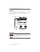
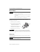
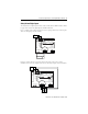
Devices with their own dedicated power supply can also be connected. Connect
the reference pole of the external power supply to the L- reference pole of the
input.
The safety state of an input is indicated by a 0 signal being passed to the user
program logic. If the test routines detect a fault in the digital inputs, a 0-signal is
processed in the user program for the defective channel. When a fault occurs, the
inputs are switched off (0) and the fault LED indicator is activated.
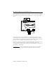
Follow the closed-circuit principle for external wiring when connecting sensors. To
create a safety state in the event of a fault, the input signals revert to the
de-energized state (0). Although the external line is not monitored, a wire break is
interpreted as a safe 0-signal.
TIP
For more information on input wiring, see the GuardPLC
System User Manual, publication number 1753-UM001.
PO PULSE TEST
L-L- L+ L+
1LS+ LS+L-234
5L-
DID1
678
19 20 21 22 23 24
1L- L-234+
789101112
25 26 27 28 29 30
24V DC
RUN
24 V DC
PROG
ERROR
FAULT
FORCE
BL
OSL
GuardPLC Ethernet
10/100 BaseT
1
()
2
()
1753-IB8XOB8
8 DC Inputs
8 DC Outputs
5L- L-678+
13 14 15 16 17 18
1L- S+24-8-
123456
DO- DO (2A) (2A)DO
L-L- L+ L+
24V DC
19 20 21 22 23 24
1LS+- L-
DI
234
24V dc
Power
Supply
COM
+
24V dc
Power
Supply
COMCOM
++
Light Curtain
(or any Safety Input Device)