Installation Instructions GuardPLC 8-Digital Inputs and 8-Digital Outputs Module Catalog Number 1753-IB8XOB8 Inside ................................................................................................page Related Documentation ............................................................................3 Description ................................................................................................4 General Safety ...................................................................
GuardPLC 8-Digital Inputs and 8-Digital Outputs Module Important User Information Solid state equipment has operational characteristics differing from those of electromechanical equipment. Safety Guidelines for the Application, Installation and Maintenance of Solid State Controls (Publication SGI-1.1 available from your local Rockwell Automation sales office or online at http://www.ab.
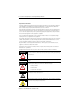
GuardPLC 8-Digital Inputs and 8-Digital Outputs Module 3 Related Documentation The table below provides a listing of publications that contain important information about GuardPLC systems. For Read this document Publication number Detailed information regarding the safety certification of the GuardPLC System. GuardPLC Controller Systems Safety Reference Manual 1753-RM002 Detailed information on installing, wiring, configuring, operating, maintaining, and troubleshooting GuardPLC systems.
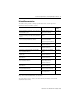
GuardPLC 8-Digital Inputs and 8-Digital Outputs Module Description The 1753-IB8XOB8 digital input/output module is a distributed I/O module for use with GuardPLC controllers. The module features 8 digital inputs, 8 positive-switching digital outputs, 2 negative-switching digital outputs, and 2 pulsed outputs, as shown below.
GuardPLC 8-Digital Inputs and 8-Digital Outputs Module ATTENTION 5 Environment and Enclosure This equipment is intended for use in a Pollution Degree 2 industrial environment, in overvoltage Category II applications (as defined in IEC publication 60664-1), at altitudes up to 2000 meters without derating. This equipment is considered Group 1, Class A industrial equipment according to IEC/CISPR Publication 11.
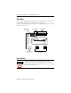
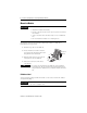
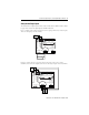
GuardPLC 8-Digital Inputs and 8-Digital Outputs Module Mount the Module IMPORTANT For effective cooling: • Mount the module horizontally. • Provide a gap of at least 100 mm (3.94 in.) above and below the module. • Select a location where air flows freely or use an additional fan. • Do not mount the module over a heating device. The module cannot be panel-mounted. Mount the module to a DIN rail by following the four steps below. 1. Hook the top slot over the DIN rail. 2.
GuardPLC 8-Digital Inputs and 8-Digital Outputs Module 7 Wire the Module The following sections describe how to wire the module. Ground the Module You must also provide an acceptable grounding path for each device in your application. For more information on proper grounding guidelines, refer to the Industrial Automation Wiring and Grounding Guidelines, publication number 1770-4.1. The I/O module is functionally grounded through its DIN rail connection.
GuardPLC 8-Digital Inputs and 8-Digital Outputs Module Connect the Voltage Supply The 24V dc voltage supply must feature galvanic isolation (in accordance with EN 60950 or UL 1950) since inputs and outputs are not electrically isolated from the processor. In order to comply with CE Low Voltage Directives (LVD), you must use either a NEC Class 2, a Safety Extra Low Voltage (SELV) or a Protected Extra Low Voltage (PELV) power supply to power this adapter. An SELV supply can’t exceed 30V rms, 42.
GuardPLC 8-Digital Inputs and 8-Digital Outputs Module 9 Safety-Related Digital Inputs The module has 8 digital inputs whose status is indicated via LED indicators. Refer to page 4 for location of digital inputs and LED indicators. LS+ is a voltage source that provides 24V dc for a group of four dry contact inputs. There are two groups on the module.
GuardPLC 8-Digital Inputs and 8-Digital Outputs Module Devices with their own dedicated power supply can also be connected. Connect the reference pole of the external power supply to the L- reference pole of the input.
GuardPLC 8-Digital Inputs and 8-Digital Outputs Module 11 Digital Input Terminals LS+ 1 2 3 4 LDI LS+ 5 6 7 8 LDI 19 20 21 22 23 24 25 26 27 28 29 30 19 20 21 22 23 24 25 26 27 28 29 30 See page 18 for the appropriate wire size.
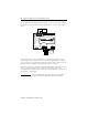
GuardPLC 8-Digital Inputs and 8-Digital Outputs Module Line Control Line control is a short-circuit and line break monitoring system (e.g., E-Stop inputs) which can be configured for the GuardPLC system. The example below shows 2 pulse test sources connected to the digital inputs (DI) of the same system. As a result, the connections to the digital inputs (DI) are monitored.
GuardPLC 8-Digital Inputs and 8-Digital Outputs Module 13 When line control detects any of the following faults, inputs are set to 0, a fault code is generated, and the FAULT LED indicator is on. • • • • short-circuit between two parallel connections reversal of two connections earth fault on one of the lines (only with earthed reference pole) line break or opening of the contacts (e.g.
GuardPLC 8-Digital Inputs and 8-Digital Outputs Module The negative-switching outputs DO4- and DO8- can supply up to 1 A at the maximum ambient temperature of 60 °C (140 ° F), 2 A at an ambient temperature of 40 °C (104 °F). With an overload, one or all of the outputs are turned off. When the overload is eliminated, the outputs are activated again.
GuardPLC 8-Digital Inputs and 8-Digital Outputs Module 15 For connection of a load, the reference pole L- of the channel group must be used. Although L- at terminals 7 and 12 and at terminals 13 and 18 are connected internally to L- on the power supply input, it is strictly recommended to use 7 and 12 for outputs 1 through 4 only and 13 and 18 for outputs 5 through 8 only. EMC testing was performed in this manner.
GuardPLC 8-Digital Inputs and 8-Digital Outputs Module Reset Pushbutton You can use the reset button if you forget the password for connecting the programming software. The pushbutton is accessible through a small round hole at the top of the housing, approximately 4 to 5 cm (1.6 to 2.0 in.) from the left rim and recessed approximately 9.5 mm (0.375 in.). IMPORTANT Activate the reset pushbutton using an insulated pin to prevent short-circuits.
GuardPLC 8-Digital Inputs and 8-Digital Outputs Module 17 Troubleshoot with LED Indicators Indicator State Condition 24V dc On 24V dc operating voltage present. Off No operating voltage. On This is the normal status of the module. A routine, which has been loaded into the module, is executed. The module processes input and output signals, carries out communication, and performs hardware and software tests. Flashing The module is in STOP mode and is not executing a routine.
GuardPLC 8-Digital Inputs and 8-Digital Outputs Module Communication Display Communication via GuardPLC Ethernet is indicated by two small LEDs integrated into all connecting sockets.
GuardPLC 8-Digital Inputs and 8-Digital Outputs Module No. of Outputs (L-) 2 (not electrically isolated), reference pole S+ Output Voltage ≥L+ minus 2V Output Current (L+) Output Current (L-) Channels 1 to 3 and 5 to 7: 0.5 A @ 60°C (140°F) Channels 4 and 8: 1 A @ 60 °C (140 °F); 2 A @ 40 °C (104 °C) Channels 4- and 8-: 1 A @ 60 °C (140 °F); 2 A @ 40 °C (104 °C) Max. lamp load: L+ channel 1-3, 5-7 L+ channel 4 and 8 L- channel 4- and 8- 10 W 25 W 25 W Max.
Radiated RF Immunity 10V/m with 1kHz sine-wave 80% AM from 80 MHz to 2000 MHz EFT/B Immunity ±2 kV @ 5 kHz on power ports ±1 kV @ 5 kHz on signal ports ±1 kV @ 5 kHz on communication ports Surge Transient Immunity ±1 kV line-line (DM) and ±1 kV line-earth (CM) on DC power ports ±500V line-line (DM) and ±1 kV line-earth (CM) on signal ports ±1 kV line-earth (CM) on communication ports Conducted RF Immunity 10Vrms with 1 kHz sine-wave 80% AM from 150 kHz to 80 MHz Enclosure Type Rating meets IP20 Me