Installation Instructions GuardPLC Digital Input/Output Module Catalog Number 1753-IB20XOB8 Topic Page Important User Information 2 About the Module 3 General Safety 3 Install the Module 4 Mount the Module 5 Ground the Module 5 Wire the Module 6 Make Connections for Safety-related Communication 12 Reset Push Button 12 Status Indicators 13 Specifications 14 Additional Resources 18
GuardPLC Digital Input/Output Module Important User Information Solid-state equipment has operational characteristics differing from those of electromechanical equipment. Safety Guidelines for the Application, Installation and Maintenance of Solid State Controls (Publication SGI-1.1 available from your local Rockwell Automation sales office or online at http://www.rockwellautomation.
GuardPLC Digital Input/Output Module 3 About the Module The 1753-IB20XOB8 digital input/output module is a 28-channel (20 inputs/8 outputs) module for use with GuardPLC controllers.
GuardPLC Digital Input/Output Module Environment and Enclosure ATTENTION: This equipment is intended for use in a Pollution Degree 2 industrial environment, in overvoltage Category II applications (as defined in IEC publication 60664-1), at altitudes up to 2000 m (6562 ft) without derating. This equipment is considered Group 1, Class A industrial equipment according to IEC/CISPR 11.
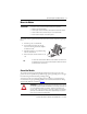
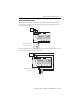
GuardPLC Digital Input/Output Module 5 Mount the Module IMPORTANT For effective cooling, mount the module following these guidelines. • • • • Mount the module horizontally. Provide a gap of at least 100 mm (3.94 in.) above and below the module. Select a location where air flows freely or use an additional fan. Do not mount the module over a heating device. The module cannot be panel-mounted. Mount the module to a DIN rail by following the steps below. 1. Hook the top slot over the DIN rail. 2.
GuardPLC Digital Input/Output Module Wire the Module The following sections describe how to connect the voltage supply and connect the inputs and outputs. Connect the Voltage Supply To comply with CE Low Voltage Directives (LVD) and UL restrictions, you must use either a Safety Extra Low Voltage (SELV), or a Protected Extra Low Voltage (PELV) power supply to power this module. A SELV supply cannot exceed 30V rms, 42.4V peak, or 60V DC under normal conditions and under single-fault conditions.
GuardPLC Digital Input/Output Module 7 Safety-related Digital Inputs The module has 20 digital inputs (DI1…DI20) whose status is indicated via status indicators. LS+ is a voltage source that provides 24V DC for a group of four dry contact inputs. There are five groups on the module.
GuardPLC Digital Input/Output Module Devices with their own dedicated power supply can also be connected. Connect the reference pole of the external power supply to the L- reference pole of the input.
GuardPLC Digital Input/Output Module Terminal Number Designation Function 19 LS+ Sensor supply for inputs 5…8 20 5 Digital input 5 21 6 Digital input 6 22 7 Digital input 7 23 8 Digital input 8 24 L- Reference pole 25 LS+ Sensor supply for inputs 9…12 26 9 Digital input 9 27 10 Digital input 10 28 11 Digital input 11 29 12 Digital input 12 30 L- Reference pole 31 LS+ Sensor supply for inputs 13…16 32 13 Digital input 13 33 14 Digital input 14 34 15 Digital i
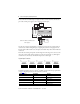
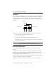
GuardPLC Digital Input/Output Module Line Control Line control is a short-circuit and line-break monitoring system, for example, E-stop inputs that can be configured for the GuardPLC system. Up to eight digital outputs (DO1…DO8) can be configured as pulsed outputs. The example below shows two pulse outputs connected to the digital inputs (DI) of the same system. As a result, the connections to the digital inputs (DI) are monitored.
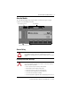
GuardPLC Digital Input/Output Module 11 Digital Output Terminals 1 2 3 4 5 6 7 8 9 10 11 12 1 2 3 4 5 6 7 8 9 10 11 12 DO L- 1 2 3 4 L(2A) DO L- 5 6 7 8 L(2A) Terminals accommodate wires up to 1.5 mm2 (16 AWG). See the terminal torque specifications on page 14. Digital outputs (DO) are connected to these terminals.
GuardPLC Digital Input/Output Module Make Connections for Safety-related Communication The module has two 10/100BaseT, RJ45 connectors on the bottom of the unit, that provide communication to the GuardPLC controller via GuardPLC Ethernet protocol. Because this is an Ethernet switch, you can daisy-chain connections from the GuardPLC module to other distributed I/O modules. The switch is auto-detect. Either crossover or straight-through cabling can be used. Star or line configurations are available.
GuardPLC Digital Input/Output Module 13 Status Indicators Indicator State 24V DC On 24V DC operating voltage present. Off No operating voltage. On This is the normal status of the controller. A routine, which has been loaded into the controller, is executed. The controller processes input and output signals, carries out communication, and performs hardware and software tests. Flashing The controller is in STOP mode and is not executing a routine. All system outputs are reset.
GuardPLC Digital Input/Output Module Specifications Technical Specifications – 1753-IB20XOB8 Module Attribute 1753-IB20XOB8 Interfaces: GuardPLC Ethernet 2 x RJ45, 10/100BaseT (with 100 Mbit/s) with integrated switch Operating voltage 24V DC, -15…20%, wss 15% from a power supply with protective separation, conforming to IEC 61131-2 requirements Isolation voltage 50V (continuous), Basic Insulation Type, I/O to Ethernet and Ethernet to DC power Wiring category(1) Category 2 on communication port
GuardPLC Digital Input/Output Module 15 Technical Specifications – 1753-IB20XOB8 Module Digital Outputs Number of outputs 8 (not electrically isolated) Output voltage range ≥ L+ minus 2V Output current channels 1…3 and 5…7: 0.
GuardPLC Digital Input/Output Module Environmental Specifications – 1753-IB20XOB8 Module Attribute 1753-L28BBB-M, 1753-L28BBB-P Temperature, nonoperating -40…85 °C (-40…185 °F) • IEC 60068-2-1 (Test Ab, Unpackaged nonoperating cold) • IEC 60068-2-2 (Test Bb, Unpackaged nonoperating dry heat) • IEC 60068-2-14 (Test Na, Unpackaged nonoperating thermal shock) Temperature, operating 0…60 °C (32…140 °F) • IEC 60068-2-1 (Test Ad, operating cold) • IEC 60068-2-2 (Test Bd, operating dry heat) • IEC 60068
GuardPLC Digital Input/Output Module 17 Certifications Certification (when product is marked)(1) 1753-IB20XOB8 c-UL-us UL Listed Industrial Control Equipment, certified for US and Canada. See UL File E65584. CE European Union 2004/108/EC EMC Directive, compliant with: • EN 61326-1 Meas./Control/Lab., Industrial Requirements • EN 61000-6.
GuardPLC Digital Input/Output Module Additional Resources The table below provides a listing of publications that contain important information about GuardPLC systems.
GuardPLC Digital Input/Output Module 19 Rockwell Automation Publication 1753-IN003C-EN-P - June 2010
Rockwell Automation Support Rockwell Automation provides technical information on the Web to assist you in using its products. At http://www.rockwellautomation.com/support/, you can find technical manuals, a knowledge base of FAQs, technical and application notes, sample code and links to software service packs, and a MySupport feature that you can customize to make the best use of these tools.