
User Manual

GuardPLC 16-Digital Inputs and 8-Digital Outputs Module 19
Publication 1753-IN011A-EN-P - October 2005
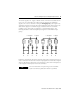
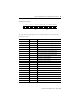
Digital Output Terminals
See page 22 for the appropriate wire size. Digital outputs are connected to the
following terminals:
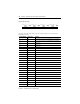
Terminal Number Designation Function
1 S+ Reference pole for negative-switching digital outputs
2 S+ Reference pole for negative-switching digital outputs
3 S+ Reference pole for negative-switching digital outputs
4 S+ Reference pole for negative-switching digital outputs
5 S- Reference pole for positive-switching digital outputs
6 S- Reference pole for positive-switching digital outputs
7 S- Reference pole for positive-switching digital outputs
8 S- Reference pole for positive-switching digital outputs
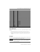
9 1- Digital output 1, negative-switching
10 1+ Digital output 1, positive-switching
11 2- Digital output 2, negative-switching
12 2+ Digital output 2, positive-switching
13 3- Digital output 3, negative-switching
14 3+ Digital output 3, positive-switching
15 4- Digital output 4, negative-switching
16 4+ Digital output 4, positive-switching
17 5- Digital output 5, negative-switching
18 5+ Digital output 5, positive-switching
19 6- Digital output 6, negative-switching
20 6+ Digital output 6, positive-switching
21 7- Digital output 7, negative-switching
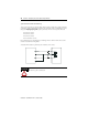
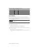
123456 87
S+
DO DO
S+ S+ S+ S- S- S- S-
91011121314 1615
1- 1+ 2- 2+ 3- 3+ 4+4- 5- 5+ 6- 6+ 7- 7+ 8+8-
17 18 19 20 21 22 2423