
User Manual

10 GuardPLC 16-Digital Inputs and 8-Digital Outputs Module
Publication 1753-IN011A-EN-P - October 2005
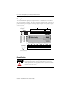
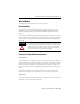
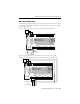
Devices with their own dedicated power supply can also be connected instead of
contacts. Connect the reference pole of the signal source to the L- reference pole of
the input.
The safety state of an input is indicated by a 0 signal being passed to the user
program logic. If the test routines detect a fault in the digital inputs, a 0-signal is
processed in the user program for the defective channel. When a fault occurs, the
inputs are switched off (0) and the fault LED indicator is activated.
PO PULSE TEST
1111
2222
123456 87
S+
DO DO
S+ S+ S+ S- S- S- S-
RUN
24 V DC
PROG
ERROR
FAULT
FORCE
BL
OSL
2
1
DO +-
4
3
6
5
8
7
GuardPLC Ethernet
10/100 BaseT
1
(—)
2
(—)
1753-IB16XOB8
16 DC Inputs
8 DC Outputs
43 44 45 46 47 48 49 50 51 52
53 54 55 56 57 58 59 60 61 62
63 64 65 66 67 68 69 70 71 72
91011121314 1615
1- 1+ 2- 2+ 3- 3+ 4+4- 5- 5+ 6- 6+ 7- 7+ 8+8-
17 18 19 20 21 22 2423
25 26 27 28 29 30 3231
LS+ LS+ 5 6 7 8 L-L-
LS+ LS+ 9 10 11 12 L-L-
LS+ LS+ 13 14 15 16 L-L-
LS+ LS+ 1 2 3 4 L-L-
33 34 35 36 37 38 39 40 41 42
DI
DI DI
L-L- L+ L+
24V DC
24V dc
Power
Supply
COM
+
COM
+
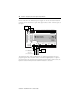
Light Curtain
(or any Safety Input Device)
24V dc
Power
Supply
COM
+
Connection of devices with dedicated
power supplies