Installation Instructions GuardPLC 16-Digital Inputs and 8-Digital Outputs Module Catalog Number 1753-IB16XOB8 Inside ................................................................................................page Related Documentation ............................................................................3 Description ................................................................................................4 General Safety .................................................................
GuardPLC 16-Digital Inputs and 8-Digital Outputs Module Important User Information Solid state equipment has operational characteristics differing from those of electromechanical equipment. Safety Guidelines for the Application, Installation and Maintenance of Solid State Controls (Publication SGI-1.1 available from your local Rockwell Automation sales office or online at http://www.ab.
GuardPLC 16-Digital Inputs and 8-Digital Outputs Module 3 Related Documentation The table below provides a listing of publications that contain important information about GuardPLC systems.
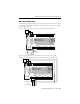
GuardPLC 16-Digital Inputs and 8-Digital Outputs Module Description The 1753-IB16XOB8 digital input/output module is a distributed I/O module for use with GuardPLC controllers. The module features 16 digital inputs, 8 two-pole (8 positive-switching and 8 negative-switching) digital outputs, and 2 pulsed outputs as shown below.
GuardPLC 16-Digital Inputs and 8-Digital Outputs Module ATTENTION 5 Environment and Enclosure This equipment is intended for use in a Pollution Degree 2 industrial environment, in overvoltage Category II applications (as defined in IEC publication 60664-1), at altitudes up to 2000 meters without derating. This equipment is considered Group 1, Class A industrial equipment according to IEC/CISPR Publication 11.
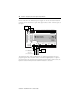
GuardPLC 16-Digital Inputs and 8-Digital Outputs Module Mount the Module IMPORTANT For effective cooling: • Mount the module horizontally. • Provide a gap of at least 100 mm (3.94 in.) above and below the module. • Select a location where air flows freely or use an additional fan. • Do not mount the module over a heating device. The module cannot be panel-mounted. Mount the module to a DIN rail by following the four steps below. 1. Hook the top slot over the DIN rail. 2.
GuardPLC 16-Digital Inputs and 8-Digital Outputs Module 7 Wire the Module The following sections describe how to wire the module. Ground the Module You must also provide an acceptable grounding path for each device in your application. For more information on proper grounding guidelines, refer to the Industrial Automation Wiring and Grounding Guidelines, publication number 1770-4.1. The module is functionally grounded through its DIN rail connection.
GuardPLC 16-Digital Inputs and 8-Digital Outputs Module Connect the Voltage Supply The 24V dc voltage supply must feature galvanic isolation (in accordance with EN 60950 or UL 1950) since inputs and outputs are not electrically isolated from the processor. In order to comply with CE Low Voltage Directives (LVD), you must use either a NEC Class 2, a Safety Extra Low Voltage (SELV) or a Protected Extra Low Voltage (PELV) power supply to power this adapter. An SELV supply can’t exceed 30V rms, 42.
GuardPLC 16-Digital Inputs and 8-Digital Outputs Module 9 Safety-Related Digital Inputs The module has 16 digital inputs whose status is indicated via LED indicators when the controller or module is in the RUN mode. Refer to page 4 for location of digital inputs and LED indicators. LS+ is a voltage source that provides 24V dc for a group of four inputs.
GuardPLC 16-Digital Inputs and 8-Digital Outputs Module Devices with their own dedicated power supply can also be connected instead of contacts. Connect the reference pole of the signal source to the L- reference pole of the input.
GuardPLC 16-Digital Inputs and 8-Digital Outputs Module 11 The sensor supplies, LS+, supply a default current of 40 mA that is buffered for 20 ms in case of a power failure. If a higher current is needed, two unbuffered supplies of 1 A can be switched on using the DI Supply [xx] system signal in the application program. This supply feeds the neighboring input channel group. The status of this supply is read and the supply is switched off if an overcurrent condition occurs.
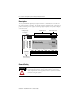
GuardPLC 16-Digital Inputs and 8-Digital Outputs Module Digital Input Terminals LS+ LS+ 1 2 3 4 L- L- 33 34 35 36 37 38 39 40 41 42 LS+ LS+ 5 6 7 8 L- L- 43 44 45 46 47 48 49 50 51 52 LS+ LS+ 9 10 11 12 L- L- 53 54 55 56 57 58 59 60 61 62 LS+ LS+ 13 14 15 16 L- L- 63 64 65 66 67 68 69 70 71 72 See page 22 for the appropriate wire size.
GuardPLC 16-Digital Inputs and 8-Digital Outputs Module 13 Terminal Number Designation Function 57 11 Digital input 11 58 12 Digital input 12 59 L- Reference pole 60 L- Reference pole 61 Ground Shield 62 Ground Shield 63 LS+ Sensor supply for inputs 13 to 16, 40 mA buffered/1 A non-buffered 64 LS+ Sensor supply for inputs 13 to 16, 40 mA buffered/1 A non-buffered 65 13 Digital input 13 66 14 Digital input 14 67 15 Digital input 15 68 16 Digital input 16 69 L- Refer
GuardPLC 16-Digital Inputs and 8-Digital Outputs Module Pulse Test Sources ATTENTION Pulse test sources must not be used as safety-related outputs. The example shows 2 pulse test sources connected to the digital inputs (DI) of the same system. As a result, the connections to the digital inputs (DI) are monitored for line control.
GuardPLC 16-Digital Inputs and 8-Digital Outputs Module 15 Pulsed Output Terminals 25 26 27 28 29 30 31 32 1 1 1 1 2 2 2 2 All PO1 and PO2 terminals are internally connected. Therefore all PO1 and PO2 terminals pulse together.
GuardPLC 16-Digital Inputs and 8-Digital Outputs Module The digital outputs can be configured as: • 1-pole switch without line monitoring • 2-pole switch with or without line monitoring • 3-pole switch (2-pole with common reference). Refer to the GuardPLC Controller Systems User Manual, publication number 1753-UM001 for more information. 1-pole Connection For 1-pole applications, all 8 DO+ and all 8 DO- outputs are available, for a total of 16 outputs.
GuardPLC 16-Digital Inputs and 8-Digital Outputs Module 17 2-pole Connection If the outputs are configured for 2-pole operation, 8 total outputs are available. Each of the 8 outputs switch both L+ and L-. 2-pole outputs (without line monitoring) are wired to both DO+ and DO- of a single channel, 2+ and 2- for example. DO 2+ DO 2- IMPORTANT The corresponding channels for the 2-pole connection must be configured for 2-pole operation using the DO[xx].2-pole system variable.
GuardPLC 16-Digital Inputs and 8-Digital Outputs Module 3-pole Connection With Line Monitoring Two 2-pole channels can support dual channel devices with only a single reference connection. If line monitoring is required, the channels must be configured in pairs, using the DO[xx][xx].in pairs system parameter. There are four pairs allowed: • • • • channels 1 and channels 3 and channels 5 and and channels 7 2, 4, 6, and 8.
GuardPLC 16-Digital Inputs and 8-Digital Outputs Module 19 Digital Output Terminals 1 2 3 4 5 6 7 8 S+ S+ S+ S+ S- S- S- S- 9 10 11 12 13 14 15 16 17 18 19 20 21 22 23 24 1- 1+ 2- 2+ 3- 3+ 4- 4+ DO 5- 5+ 6- 6+ 7- 7+ 8- 8+ DO See page 22 for the appropriate wire size.
GuardPLC 16-Digital Inputs and 8-Digital Outputs Module Terminal Number Designation Function 22 7+ Digital output 7, positive-switching 23 8- Digital output 8, negative-switching 24 8+ Digital output 8, positive-switching Reset Pushbutton You can use the reset button if you forget the password for connecting the programming software. The pushbutton is accessible through a small round hole at the top of the housing, approximately 4 to 5 cm (1.6 to 2.0 in.
GuardPLC 16-Digital Inputs and 8-Digital Outputs Module 21 Troubleshoot with LED Indicators Indicator State Condition 24V dc On 24V dc operating voltage present. Off No operating voltage. On This is the normal status of the module. A routine, which has been loaded into the module, is executed. The module processes input and output signals, carries out communication and performs hardware and software tests. Flashing The module is in STOP mode and is not executing a routine.
GuardPLC 16-Digital Inputs and 8-Digital Outputs Module Specifications Module Response Time ≥ 10 ms Interface: GuardPLC Ethernet 2 x RJ-45, 10/100BaseT (with 100 Mbps) with integrated switch Operating Voltage 24V dc, -15% to +20%, wss ≤15% Current Consumption max. 10 A (with max. load) 0.6 A @ 24V idle current Isolation Voltage No isolation between circuits Wiring Category (1) Wire Size category 2 on communications ports, signal ports, and power ports I/O – 16 AWG (1.5 mm2) to 26 AWG (0.
GuardPLC 16-Digital Inputs and 8-Digital Outputs Module Total Output Current 23 max. 8 A Pulsed Outputs No. of Outputs 2 (not electrically isolated) Output Voltage ≥L+ minus 4V Output Current (L+) Approx. 60 mA Minimum Load none Switching Time ≤100 micro-seconds Overload Response 2 x ≥ 19.2V, short-circuit current 60 mA @ 24V Environmental Conditions Storage Temperature : -40...+85 °C (-40...
Certifications(2) (when product is marked) c-UL-us UL Listed Industrial Control Equipment, certified for US and Canada CE European Union 89/336/EEC EMC Directive, compliant with: • EN 61000-6.2; Industrial Immunity • EN 61000-6-4; Industrial Emissions C-Tick Australian Radiocommunications Act, compliant with: AS/NZS CISPR 11; Industrial Emissions TÜV TÜV Certified for Functional Safety (1) Use this Conductor Category information for planning conductor routing.