
Safety Scanner for GuardPLC Controllers User Manual


Publication 1753-UM002A-EN-P - July 2005
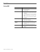
10-12 Monitor Status
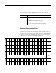
Connection Status Signals
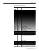
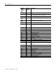
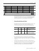
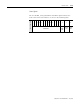
Each standard status table is presented as a collection of 64 bits,
contained within 2 DWORD device signals, as shown in the table
below. The left column shows the signal names as they appear in
RSLogix Guard PLUS!.
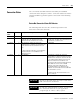
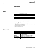
DeviceNet Interface Status
The DeviceNet Interface Status bits provide general status information
for the scanner’s DeviceNet Interface, as described in the table below.
_Std_FaultTable_1
31 30 29 28 27 26 25 24 23 22 21 20 19 18 17 16 15 14 13 12 11 10 9 8 7 6 5 4 3 2 1 0
Bit Position
31 30 29 28 27 26 25 24 23 22 21 20 19 18 17 16 15 14 13 12 11 10 9 8 7 6 5 4 3 2 1 0
Node
Address
_Std_FaultTable_2
31 30 29 28 27 26 25 24 23 22 21 20 19 18 17 16 15 14 13 12 11 10 9 8 7 6 5 4 3 2 1 0
Bit Position
63 62 61 60 59 58 57 56 55 54 53 52 51 50 49 48 47 46 45 44 43 42 41 40 39 38 37 36 35 34 33 32
Node
Address
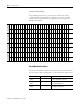
_Std_IdleTable_1
31 30 29 28 27 26 25 24 23 22 21 20 19 18 17 16 15 14 13 12 11 10 9 8 7 6 5 4 3 2 1 0
Bit Position
31 30 29 28 27 26 25 24 23 22 21 20 19 18 17 16 15 14 13 12 11 10 9 8 7 6 5 4 3 2 1 0
Node
Address
_Std_IdleTable_2
31 30 29 28 27 26 25 24 23 22 21 20 19 18 17 16 15 14 13 12 11 10 9 8 7 6 5 4 3 2 1 0
Bit Position
63 62 61 60 59 58 57 56 55 54 53 52 51 50 49 48 47 46 45 44 43 42 41 40 39 38 37 36 35 34 33 32
Node
Address
Status Bit Data Type Attribute Value Description
Communications
Failure
BOOL 0 = Normal
1 = Bus Off condition is present
DeviceNet Power
Failure
BOOL 0 = Normal
1 = No DeviceNet power.
Duplicate MAC
Failure
BOOL 0 = Normal
1 = Duplicate MAC Failure