
Safety Scanner for GuardPLC Controllers User Manual


Publication 1753-UM002A-EN-P - July 2005
Monitor Status 10-11
User application logic only needs to consider status bits associated
with connections present in the scanner’s configuration. The list of
configured connections can be obtained from the RSNetWorx for
DeviceNet report feature by selecting File>Generate Report.
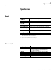
Standard DeviceNet Connection Status
The Faulted Node Table and Idle Node Table attributes of the Scanner
Configuration Object (class 0x90) contain standard DeviceNet
connection status information as described in the following table.
For nodes with more than one connection type enabled (that is,
connections with both an input and output connection configured),
the status bit reflects the logical ‘OR’ of the status for each configured
connection.
User application program logic only needs to consider status bits
associated with nodes that have one or more connections. The status
bits of nodes without any connections may be ignored. The list of
configured connections can be obtained from the RSNetWorx for
DeviceNet report feature by selecting File>Generate Report.
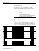
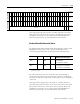
_Safe_IdleTable_2
31 30 29 28 27 26 25 24 23 22 21 20 19 18 17 16 15 14 13 12 11 10 9 8 7 6 5 4 3 2 1 0
Bit Position
64 63 62 61 60 59 58 57 56 55 54 53 52 51 50 49 48 47 46 45 44 43 42 41 40 39 38 37 36 35 34 33
Connection
Number
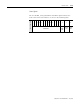
_Safe_IdleTable_3
31 30 29 28 27 26 25 24 23 22 21 20 19 18 17 16 15 14 13 12 11 10 9 8 7 6 5 4 3 2 1 0
Bit Position
RESERVED 66 65
Connection
Number
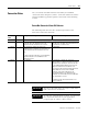
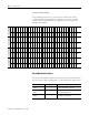
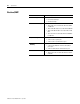
Name Attribute Data Type Access
Attribute Value Description
(1)
(1) The bit offset in the table corresponds to the node number. For example, bit 0 corresponds to node 0…bit 15
corresponds to node 15.
Faulted Node
Table
0x10 a Array of
BOOL
Get 0 = The device is not faulted or is
not configured.
1 = The device is faulted.
Idle Node
Table
0x11 b Array of
BOOL
Get 0 = The device is not in Idle mode
or the device is not configured.
1 = The Device is in Idle mode.