
Safety Scanner for GuardPLC Controllers User Manual

Publication 1753-UM002A-EN-P - July 2005
Before You Begin 1-5
Since this colorization only applies to the Connect Signals dialogs
available from the HSP protocol context menu, we strongly
recommend that when using both standard and safety signals in your
application, you use a naming convention to visually distinguish
between standard and safety signals throughout the RSLogix Guard
PLUS! programming environment. For example, use a prefix of ‘std_’
for any signals that are standard and a prefix of ‘safe_’ for any signals
that are safety-related.
Role of RSNetWorx for
DeviceNet and RSLogix
Guard PLUS!
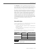
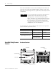
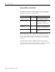
RSNetWorx for DeviceNet, version 6.x or higher, is the configuration
tool for the 1753-DNSI on the DeviceNet Safety network. RSNetWorx
for DeviceNet can connect to the safety scanner directly over the
DeviceNet network via an RS-232 interface (1770-KFD module) or PC
card (1784-PCD or -PCID) or through another network using a bridge
device. A bridge can be either a single device with communication
ports for two different networks, or separate communication devices
in the same chassis.
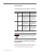
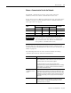
RSNetWorx for DeviceNet exchanges signal information with RSLogix
Guard PLUS!, the configuration and programming tool for the
GuardPLC controller. The Scanner Signals and Target Connections
IMPORTANT
The red/blue colorization is not a guarantee that a
signal is a safety signal. It only indicates which type
of connection the signal was transferred over. The
classification of the end node must also be
considered. Any signal that appears in the (blue)
standard Connect Signals window and is regarded as
safety at the end device must be treated as standard
in your application. Any signal that appears in the
(red) safety Connect Signals window and is regarded
as standard at the end device must be treated as
standard in your application. In order for a signal to
be regarded as a safety value in your application, the
end device configuration must treat it as safety and it
must be transferred over a DeviceNet Safety
connection.
L+ L-
24V dc
123456
1234
1L-
L-L- L+ L+
L-DO 2
(2A)
34
1LS+- LS+ LS+ LS+ LS+L-
D1
234
56
13 14 15 16 17 18
5L-
D1
678
19 20 21 22 23 24
9L-
D1
1011 12
25 26 27 28 29 30
13 L-
D1
1415 16
31 32 33 34 35 36
17 L-
D1
1819 20
37 38 39 40 41 42
19 20 21 22 23 2413 14 15 16 23 24 25 26 27 28 29 30 31 32 33 34 35 36 37 38 39 40 41 42
789101112
78910
5L- L-DO 6
(2A)
7 8
11 12
COMM3
ASCII/HSP
RS-485
24V DC
COMM2
COMM1
RUN
24 V DC
GuardPLC Ethernet
10/100 BaseT
PROG
ERROR
FAULT
FORCE
BL
OSL
PROFIBUS
3
(—)
4
(—)
3
(—)
4
(—)
1753-L28BBBM
20 DC Inputs
8 DC Outputs
DeviceNet
PC with RSNetWorx for
DeviceNet Software
PC with RSLogix Guard
PLUS! Software
1770-KFD PC
Communication
Module
GuardPLC Controller
1753-DNSI