Installation Instructions SynchLink Base Block Catalog Number 1751-SLBA This document describes how to install and use the 1751-SLBA SynchLink™ base block.
SynchLink Base Block Important User Information Because of the variety of uses for the products described in this publication, those responsible for the application and use of this control equipment must satisfy themselves that all necessary steps have been taken to assure that each application and use meets all performance and safety requirements, including any applicable laws, regulations, codes and standards.
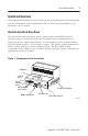
SynchLink Base Block 3 SynchLink Overview We designed the SynchLink system to provide the synchronization and coordination of drive and motion control applications that are based on ControlLogix™ and PowerFlex 700s™ stations. About the SynchLink Base Block The base block converts optical signals coming from a SynchLink station to electrical signals, and then re-times and retransmits them simultaneously to a maximum of four 4-port splitter blocks. It also supplies power to splitter blocks.
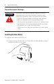
SynchLink Base Block Prevent Electrostatic Discharge ATTENTION ! Electrostatic discharge can damage integrated circuits or semiconductors if you touch backplane connector pins. Follow these guidelines when you handle the base block: • • • • • • Touch a grounded object to discharge static potential. Wear an approved wrist-strap grounding device. Do not touch the backplane connector or connector pins. Do not touch circuit components inside the base block. If available, use a static-safe work station.
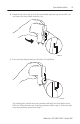
SynchLink Base Block 5 2. Hook the lip of on the rear of the base block onto the top of the DIN rail and rotate the base block onto the rail. 31203b-M 3. Press the base block down to the DIN rail until flush. 31203c-M The locking tab should snap into position and lock the base block to the DIN rail. If the tab does not snap into position, follow step 4. If the tab does snap into position, proceed to step 5.
SynchLink Base Block 4. Use a screwdriver to move the locking tab down while you press the base block flush onto the DIN rail. Release the locking tab to lock the base block into place. If necessary, push up on the locking tab to lock the base block into place. 5. Once you attach the base block to the DIN rail, slide the base block to the left. ATTENTION ! Be certain that you secure the base block and 4-port Splitter blocks together with DIN rail anchors.
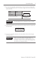
SynchLink Base Block 7 2. Pre-wire the removable connector plug as shown on the base block label. The wire length between the 24V dc power supply and the base block must be less than 3m. Connect To pin +24V dc 4 24V dc Common 3 Pins 1 and 2 are not connected. Pin 1 Pin 2 Pin 3 Pin 4 Power Supply and digital Input Connector (front view) 31248-M IMPORTANT Do not connect 24V dc Common to Chassis Ground. 3.
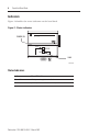
SynchLink Base Block Indicators Figure 2 identifies the status indicators on the base block.
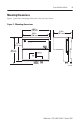
SynchLink Base Block 9 Mounting Dimensions Figure 3 provides mounting dimensions for the base block. Figure 3 - Mounting dimensions 4.084 in. (104 mm) 3.94 in. (100 mm) 2.76 in. (70.1 mm) 3.6 in. (91.4 mm) 3.81 in.
SynchLink Base Block European Communities (EC) Directive Compliance If this product has the CE mark it is approved for installation within the European Union and EEA regions. It has been designed and tested to meet the following directives.
SynchLink Base Block 11 Hazardous Location information The following information applies when operating this equipment in hazardous locations: Products marked “CL I, DIV 2, GP A, B, C, D” are suitable for use in Class I Division 2 Groups A, B, C, D, Hazardous Locations and nonhazardous locations only. Each product is supplied with markings on the rating nameplate indicating the hazardous location temperature code.
SynchLink Base Block Informations sur l’utilisation de cet équipement en environnements dangereux : Les produits marqués « CL I, DIV 2, GP A, B, C, D » ne conviennent qu’à une utilisation en environnements de Classe I Division 2 Groupes A, B, C, D dangereux et non dangereux. Chaque produit est livré avec des marquages sur sa plaque d’identification qui indiquent le code de température pour les environnements dangereux.
SynchLink Base Block 13 Rockwell Automation Support Rockwell Automation offers support services worldwide, with over 75 sales/support offices, over 500 authorized distributors, and 260 authorized systems integrators located throughout the United States alone, plus Rockwell Automation representatives in every major country around the world.
SynchLink Base Block Specifications Power Supply To comply with CE Low Voltage directives, you must use a Safety Extra Low Voltage (SELV) or a Protected Extra Low Voltage (PELV) power supply to power this base block. Use a NEC/CEC Class 2 power supply in order to comply with UL and CSA requirements. Input Voltage Rating 0.6A @ 24V dc nominal Output Voltage Rating 1.2A @ 5.1V dc nominal Input Voltage Range 20V dc to 30V dc A regulated power supply is recommended.
SynchLink Base Block Agency Certifications When product is marked: 15 Listed Industrial Control Equipment Certified Process Control Equipment Certified Class I, Division 2, Group A, B, C, D Marked for all applicable directives marked for all applicable acts N223 (1) (2) This product must be mounted within a suitable system enclosure to prevent personal injury resulting from accessibility to live parts. The interior of this enclosure must be accessible only by the use of a tool.
Notes: Allen-Bradley, ControlLogix, PowerFlex 700s, and SynchLink are trademarks of Rockwell Automation. Publication 1751-IN001A-EN-P - March 2001 PN 957345-10 © 2001 Rockwell International Corporation. Printed in the U.S.A.