Installation Instructions SynchLink Bypass Switch Block Catalog Number 1751-SLBP This document describes how to install and use the 1751-SLBP SynchLink bypass switch block.
SynchLink Bypass Switch Block Important User Information Because of the variety of uses for the products described in this publication, those responsible for the application and use of these products must satisfy themselves that all necessary steps have been taken to assure that each application and use meets all performance and safety requirements, including any applicable laws, regulations, codes and standards.
SynchLink Bypass Switch Block ATTENTION ! 3 Environment and Enclosure This equipment is intended for use in a Pollution Degree 2 industrial environment, in overvoltage Category II applications (as defined in IEC publication 60664-1), at altitudes up to 2000 meters without derating. This equipment is considered Group 1, Class A industrial equipment according to IEC/CISPR Publication 11.
SynchLink Bypass Switch Block SynchLink Overview We designed the SynchLink system to provide the synchronization and coordination of drive and motion control applications that are based on ControlLogix and PowerFlex 700s stations. About the SynchLink Bypass Switch Block Use the SynchLink bypass switch block in SynchLink daisy-chain configuration where a station, or group of stations, needs to be temporarily disconnected from the SynchLink system without physical re-configuration of the cable system.
SynchLink Bypass Switch Block 5 Prevent Electrostatic Discharge ATTENTION ! This equipment is sensitive to electrostatic discharge, which can cause internal damage and affect normal operation. Follow these guidelines when you handle this equipment: • • • • • • Touch a grounded object to discharge potential static. Wear an approved grounding wriststrap. Do not touch connectors or pins on component boards. Do not touch circuit components inside the equipment. If available, use a static-safe workstation.
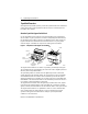
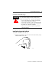
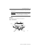
SynchLink Bypass Switch Block 2. Hook the lip of on the rear of the switch block onto the top of the DIN rail and rotate the switch block onto the rail. 31203b-M 3. Press the bypass switch block down to the DIN rail until flush. The locking tab should snap into position and lock the switch block to the DIN rail. If the tab does not snap into position, follow step 4. If the tab does snap into position, proceed to step 5.
SynchLink Bypass Switch Block 4. Use a block block block 7 screwdriver to move the locking tab down while you press the switch flush onto the DIN rail. Release the locking tab to lock the switch into place. If necessary, push up on the locking tab to lock the switch into place. 5. Use DIN rail end anchors to secure the switch block. (Allen-Bradley catalog number 1492-EAH35) ATTENTION Be certain that you secure the bypass switch block with DIN rail anchors.
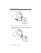
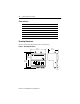
SynchLink Bypass Switch Block Wiring the Bypass Switch Block ATTENTION Do not look directly into the fiber ports or fiber cable. Light levels may cause damage to eyesight. The bypass switch block is a Class 1 LED product. ! To wire the bypass switch block and connect power: 1. Connect pre-terminated fiber optic cables as shown. Connect To RxIN1 Upstream station transmitter TxOUT1 Downstrean station receiver RxIN2 Local station transmitter TxOUT2 Local station receiver 2.
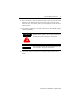
SynchLink Bypass Switch Block 9 4. Screw the removable connector to the switch block with the left and right mounting screws. IMPORTANT Make sure the switch block is attached and secured prior to applying power to the switch block. Failure to do so may cause damage to the switch block. Indicators Figure 2 identifies the status indicators on the switch block.
SynchLink Bypass Switch Block Status Indicators Indicator When LED is ON Power ON 24V dc power is applied to the switch block Bypass ON block is in the Bypass mode RxIN1 optical signals are received from the upstream station TxOUT1 optical signals are transmitted to the downstream station RxIN2 optical signals are received from the local station TxOUT2 optical signals are transmitted to the local station Mounting Dimensions Figure 3 provides mounting dimensions for the switch block.
SynchLink Bypass Switch Block 11 Hazardous Location The following information applies when operating this equipment in hazardous locations: Informations sur l’utilisation de cet équipement en environnements dangereux : Products marked “CL I, DIV 2, GP A, B, C, D” are suitable for use in Class I Division 2 Groups A, B, C, D, Hazardous Locations and nonhazardous locations only. Each product is supplied with markings on the rating nameplate indicating the hazardous location temperature code.
SynchLink Bypass Switch Block Rockwell Automation Support Rockwell Automation offers support services worldwide, with over 75 sales/support offices, over 500 authorized distributors, and 260 authorized systems integrators located throughout the United States alone, plus Rockwell Automation representatives in every major country around the world.
SynchLink Bypass Switch Block 13 Specifications Power Supply To comply with CE Low Voltage directives, you must use a Safety Extra Low Voltage (SELV) or a Protected Extra Low Voltage (PELV) power supply to power this bypass switch block. Use a NEC/CEC Class 2 power supply in order to comply with UL and CSA requirements. Power Supply Rating 0.1A @ 24V dc nominal Power Supply Range 20V dc to 30V dc A regulated power supply is recommended.
SynchLink Bypass Switch Block Power Conductors Wire Size 12 gauge maximum, 24 gauge minimum (#12 AWG to 24 AWG), stranded Category 2(12) Maximum Length 3 meters Digital Input isolated, sinking ON-State Voltage 12V dc minimum 24V dc nominal 30V dc maximum ON-State Current 12.0mA nominal at 24V dc OFF-State Voltage 8.
SynchLink Bypass Switch Block (13) (14) 15 Shielded cable required. See Product Certification link at www.ab.com for Declarations of Conformity, Certificates, and other certification details. Allen-Bradley, ControlLogix, PowerFlex 700s, and SynchLink are trademarks of Rockwell Automation. ControlNet is a trademark of ControlNet International.
Publication 1751-IN003B-EN-P - September 2001 Supersedes Publication 1751-IN003A-EN-P - March 2001 PN 957626-14 Copyright © 2001 Rockwell Automation. All rights reserved. Printed in the U.S.A.