DataSite Configured Panel Installation Instructions 1748 DataSite Configured Panel
Important User Information Solid state equipment has operational characteristics differing from those of electromechanical equipment. Safety Guidelines for the Application, Installation and Maintenance of Solid State Controls (publication SGI-1.1 available from your local Rockwell Automation sales office or online at http://literature.rockwellautomation.com) describes some important differences between solid state equipment and hard-wired electromechanical devices.
Table of Contents Preface Who Should Use this Manual . . . . . . . . . . . . . . . . . . . . . . . . . . . . . . . . . 5 Purpose of this Manual . . . . . . . . . . . . . . . . . . . . . . . . . . . . . . . . . . . . . . 5 Related Documentation . . . . . . . . . . . . . . . . . . . . . . . . . . . . . . . . . . . . . . 5 Common Techniques Used in this Manual. . . . . . . . . . . . . . . . . . . . . . . 6 Chapter 1 Overview Introduction . . . . . . . . . . . . . . . . . . . . . . . . . . . . . . . . . . .
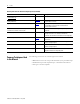
Table of Contents Chapter 6 Troubleshooting Field Repairs and Replacement Procedures . . . . . . . . . . . . . . . . . . . . . 33 Troubleshooting the DataSite Configured Panel . . . . . . . . . . . . . . . . . 34 Troubleshooting the Solar Controller of the DataSite Configured Panel . . . . . . . . . . . . . . . . . . . . . . . . . . . . . . . . . . . . . . . . . . . . . . . . . . . . 36 Step 1: Check environment . . . . . . . . . . . . . . . . . . . . . . . . . . . . . . .
Preface Read this preface to familiarize yourself with the rest of the manual. It provides information concerning: • • • • Who Should Use this Manual who should use this manual the purpose of this manual related documentation conventions used in this manual Use this manual if you are responsible for designing, installing, programming, or troubleshooting DataSite configured panels. You should have a basic understanding of electrical circuitry and familiarity with relay logic.
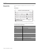
Preface Related publications for DataSite configured panel (Continued) Pub. Title Pub. Number Description Modbus Protocol Specifications Available from www.modbus.org — Information about the Modbus protocol. Allen-Bradley Programmable Controller Grounding and Wiring Guidelines 1770-4.1 In-depth information on grounding and wiring Allen-Bradley programmable controllers. Application Considerations for Solid-State Controls SGI-1.
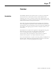
Chapter 1 Overview Introduction Allen-Bradley industrial control panels consist of a metal or polycarbonate enclosure that house a wide variety of factory-wired industrial control equipment such as motor controllers, switches, relays, auxiliary devices and programmable logic controllers. The panels may also include a disconnecting means and motor branch circuit protective devices. These enclosures can be wall-mounted or free-standing (pole mounted) to meet varying application requirements.
Overview Nameplate Data Each control panel has a nameplate located on the enclosure or enclosure door. Unit Nameplate DATASITE CONFIGURED PANEL CATALOG NO. SERIES A-B SERIAL NO. ENCL. TYPE. LINE [V] HZ. PHASES FULL LOAD [A] LARGEST LOAD [A] HAZ. LOC TEMP. CODE WIRING DIAGRAM Allen-Bradley MADE IN ____________ The following product information is provided on the panel nameplate. Information Fields on Panel Nameplate Publication 1748-IN001B-EN-P - May 2009 Field Description CATALOG NO.
Overview cULus Marking Each industrial control panel, where applicable, will bear a cULus Listing Mark. Panels that do not meet cULus Listing will not bear a label. ATTENTION Environmental Ratings 9 Suitable for use in Class I Division 2, Groups A, B, C, and D Hazardous Locations, or Nonhazardous Locations only.
Overview Components This table provides a list of the main components in the DataSite configured panel and their descriptions. The numbers in the Number column refer to the components as shown on page 11. DataSite Configured Panel Components (All Options Shown) Number Component Description 1 DataSite controller Low power logic device used for calculation and storing of field attached measuring devices.
Overview 11 DataSite Configured Panel Components Front view (with door closed) Side view (with door closed) Allen-Bradley 7 9 13 WARNING CAUTION Allen-Bradley 44747 44746 Inside view Mounting Holes 1 2 12 11 8 3 Mounting Holes 6 10 Note: (3) is located beneath (8) and is not visible in this drawing.
Overview Panel Layout This figure shows a typical layout of the DataSite configured panel.
Overview 13 Receiving, Handling, and Storage For a complete list of receiving, handling and storage instructions, please refer to "Receiving, Handling, and Storage Industrial Control Panels Instructions", publication 1000-IN001. Catalog Number Explanation The following chart describes the parts that make up the catalog number for a DataSite configured panel.
Overview Notes: Publication 1748-IN001B-EN-P - May 2009
Chapter 2 Install and Wire the Panel This chapter provides you with an overview of the installation and wiring of the DataSite configured panel. Environment and Enclosure Most applications require installation in an industrial enclosure to reduce the effects of electrical interference and environmental exposure. Locate your controller as far as possible from power lines, load lines, and other sources of electrical noise such as hard-contact switches, relays, and AC motor drives.
Install and Wire the Panel Depending on the options chosen, the dimensions for the DataSite configured panel are 59.69 x 41.28 x 26.67 cm (23.5 x 16.25 x 10.5 in.) or 59.69 x 41.28 x 20.96 cm (23.5 x 16.25 x 8.25 in.). Panel Dimensions Front view (with door closed) Side view (with door closed) Allen-Bradley WARNING CAUTION Allen-Bradley 45.72 cm (18.00 in.) 44752 44751 Note: Depending on options chosen, the panel depth is 26.67 cm (10.50 in.) or 20.96 cm (8.25 in.). Inside view 57.
Install and Wire the Panel Panel Weights 17 The weight of the DataSite configured panel depends on the battery included. The following are the approximate weights of the panel for each battery option: • With a 14 Ah battery: 9.07 kg (20 lb) • With a 28 Ah battery: 13.61 kg (30 lb) • With a 56 Ah battery: 20.
Install and Wire the Panel The following figures show a typical DataSite controller system installation and a typical pole-mounted arrangement. Typical DataSite Controller System Solar Cell Serial or Ethernet Comms Antenna Radio Controller 12V DC Battery Bank IMPORTANT Cable length between panel and antenna must not exceed 30.5m (100 ft). Typical DataSite Configured Panel Pole Mounting Note: Picture may not match actual product.
Install and Wire the Panel Control Panel Wiring 19 Wiring details for the control panel can be found on the schematics shipped with your panel. The selector switch on the door serves as a disconnecting device to energize or de-energize power to the unit. When installing field devices, over-current protection must be considered. Refer to NEC 2005 article 240 regarding the use of over-current protection for field installed devices.
Install and Wire the Panel Incoming/Outgoing Wire Installation Allowable incoming and outgoing voltages can range from 0V DC to 24V DC. IMPORTANT Any conduit or cable entering or leaving the DataSite configured panel which is not deemed non-incendive must be held in conduit to maintain the UL Class I Division 2 Listing of that control panel. For details about field wiring apparatus, refer to the control drawing in the DataSite Hardware User Manual, publication 1758-UM001.
Install and Wire the Panel Antenna and Antenna Cable Installation 21 Use only antennas approved by radio manufacturers. The following are some common types of antennas: • Directional (yagi, parabolic) • Omni-directional (dipole) Gain is specified in dBd or dBi and achieved by directing (focusing) radio frequency (RF) emission. Emission patterns must be considered such that other sites are within the focused area. Antenna cables should be selected to match required length.
Install and Wire the Panel Notes: Publication 1748-IN001B-EN-P - May 2009
Chapter 3 Final Checklist Before Energizing This chapter provides guidance for the start-up of a newly installed DataSite configured panel. It is recommended to make an itemized list including the following information: • • • • Serial number Number of units and their locations System voltage Other important data. This itemized list should be saved in a file along with other data for the installation of the DataSite controller, such as component manuals, radio manuals, and wiring diagrams.
Final Checklist Before Energizing Pre-energizing Check Procedure 1. Remove all blocks or temporary holding means used for shipping all component devices. 2. Inspect the enclosure and units for damage. If structural damage is present, contact Rockwell Automation Technical Support. 3. Check and verify that the panel is properly installed, as described in Chapter 2. Inspect and verify that it is level, supported, and anchored (if necessary or required).
Final Checklist Before Energizing 25 8. For applications requiring power fuses, install the fuses in the fusible switches in accordance with the NEC application requirements. All fuses must be completely inserted in the fuse clips. Fuses may only be inserted after the location has been determined to be non-hazardous. 9. Component devices may require unique start-up procedures. For specific start-up guidance, refer to the DataSite Hardware User Manual, publication 1758-UM001.
Final Checklist Before Energizing Notes: Publication 1748-IN001B-EN-P - May 2009
Chapter 4 Energizing and Commissioning This chapter provides you with instructions for energizing the DataSite configured panel. Energizing Equipment This procedure is provided as a general guidance for energizing a newly installed DataSite configured panel. IMPORTANT ATTENTION Perform this procedure after the Final Check procedure has been completed. See Chapter 3, Final Checklist Before Energizing. Energizing a DataSite controller for the first time is potentially dangerous.
Energizing and Commissioning 2. Energize the remote power source of the DataSite controller. 3. Energize the main devices followed by the feeder devices and the branch circuit devices. Always energize from the source of the system, working toward the loads. ATTENTION After all of the disconnect devices have been closed, loads may be energized.
Chapter 5 Maintaining the DataSite Configured Panel A periodic maintenance program should be established for the DataSite configured panel to avoid unnecessary downtime. The frequency of service to your DataSite configured panel will depend upon the equipment usage and the environment in which it operates. The following is a suggested checklist and can be used to establish a maintenance program. ATTENTION Maintenance Checklist De-energize the DataSite configured panel before servicing.
Maintaining the DataSite Configured Panel 4. Check for the proper function and freedom of movement (no sticking or binding) for the disconnect switch (800H), and defeater mechanisms. Replace broken, deformed, malfunctioning or badly worn parts or assemblies. WARNING Follow NFPA 70E, 2004 safety guidelines when working on energized equipment.
Maintaining the DataSite Configured Panel 31 Battery intervals may vary with the addition of external loads to the system or rapid changes in ambient temperature. Periodic maintenance and measurement of battery life should be done to ensure system reliability. 10. Check all fuses. If replacing fuses, install the same type and rated fuse that was originally furnished with the DataSite configured panel. 11. Remove accumulated dust and dirt from structure and individual units by vacuuming.
Maintaining the DataSite Configured Panel Maintenance after a Fault Condition Ensure the location is free of any hazardous gasses then disconnect all power sources to the DataSite configured panel before diagnosing the cause of a fault condition. For more details, refer to NFPA 70E, 2004 “Safety Related Work Practices”. Fault conditions (lightning strike, over-current situation) can cause damage to control equipment.
Chapter 6 Troubleshooting You can use this chapter as a diagnostic tool to aid in the troubleshooting of the DataSite configured panel. A table and a step-by-step guide are provided. The assumption has been made that the DataSite configured panel had been properly installed and operating prior to the occurrence of a fault. ATTENTION Troubleshooting in a hazardous location must be done by a qualified field personnel.
Troubleshooting Troubleshooting the DataSite Configured Panel The following table covers a brief technical approach to verifying the functionality of the following components: • • • • • DataSite controller Human-machine interface (HMI) Transmit radio Batteries Solar charge controller It is recommended that troubleshooting of the DataSite configured panel begin with the use of the following troubleshooting table for a more systematic and modular approach.
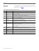
Troubleshooting 35 Troubleshooting the DataSite Configured Panel Problem Component Possible Cause Check Action HMI (8) does not power on Display Wire fault Check all wiring associated with the HMI. Ensure that the protective fuse has not blown and that the DC-DC converter is working properly. Check wiring. Contact Rockwell Automation Technical Support if the HMI or a related component needs to be replaced.
Troubleshooting Troubleshooting the Solar Controller of the DataSite Configured Panel Depending on the system it will be normal for the solar controller to go a long period of time with or without charging. The function of the solar controller is to regulate the charging of the batteries in the DataSite configured panel. After a long period without sunlight, the solar controller will allow the solar panel to charge the batteries of the DataSite configured panel for an extended period of time.
Troubleshooting 37 Step 1: Check environment Ensure that the environment is clear of all hazards including explosive gases before opening the DataSite configured panel. Refer to NFPA 70E, 2004 Safety Guidelines when servicing the DataSite configured panel equipment. Step 2: Check solar panel output Check the solar panel output to ensure that the solar array is connected and working properly.
Troubleshooting Step 4: Test condition of power transistors in solar controller Test the condition of the power transistors in the solar controller. 1. With the solar controller completely disconnected from the DataSite configured panel, make these connections. a. Use a variable power supply set to 20V DC, 0.5 mA. b. Connect the + VDC Power Supply terminal to the ARRAY(+) input terminal of the solar charge controller (3). c.
Troubleshooting 39 Step 6: Test temperature compensation cable Test the temperature compensation cable which is affixed to the side of the backup batteries ((4) on page 11.) 1. With the solar controller completely disconnected from the DataSite configured panel, make these connections. a. Use a variable power supply set to 20V DC, 0.5 mA. b. Connect the + VDC Power supply terminal to ARRAY (+) input terminal of the solar controller. c.
Troubleshooting Troubleshooting the Human-machine Interface (HMI) When equipped, the HMI (8) will display information programmed to read the different parameters of the DataSite. The default program in the HMI is empty. The units must be programmed before use. This section gives an overview of troubleshooting when the HMI is not working. Step 1: Test the condition of ’ON’ push button for the HMI With the main power switch in the ON position, conduct the following test: 1.
Troubleshooting 41 b. If 12V DC is not present at the DC-DC converter, check the following: – Check to see that the fuse 3FU has not opened. – If the fuse has opened, inspect the wiring for cuts or frays and replace if necessary. Contact Rockwell Technical Support for more details. 3. Check all cables and wires associated with the HMI. a. The HMI communicates with the DataSite controller via a serial communication RS232 cable. If this cable is frayed or kinked, the communication may be halted.
Troubleshooting Moisture Penetration Moisture is the leading cause of faults associated with outdoor panel applications. The introduction of moisture or condensate in the DataSite configured panel may cause components in the panel to wear out prematurely. Moisture in the panel will cause corrosion of some of the components, making the DataSite configured panel unreliable.
Chapter 7 Renewal Parts Renewal Parts Stocking Program A Renewal Parts Stocking Program for your DataSite configured panel is recommended in conjunction with a maintenance program. This is important for minimizing expensive downtime and facilitating critical repairs. The following are factors to consider when developing an effective Renewal Parts Stocking Program: 1. Frequency of “ON-OFF” cycling, 2. Duration of “ON” or operating time, 3.
Renewal Parts Replacement Parts Publication 1748-IN001B-EN-P - May 2009 This table lists the replacement parts available, the manufacturers, and the corresponding Rockwell part numbers.
Appendix A DataSite Configured Panel Battery This appendix provides the following information: • Environmental Effects on Charge Capacity • Battery Life Expectancy Battery capacity is a function of ambient temperature and the rate of discharge. The batteries supplied for the DataSite configured panels are rated at a 100% capacity at 20 °C (68 °F). As shown in the installation section, the increase in ambient temperature will increase the available capacity of the battery.
DataSite Configured Panel Battery Charging and Discharging The batteries supplied with the DataSite configured panel are designed for discharge in temperatures ranging from -40 °C to 60 °C (-40 °F to 140 °F) and to be charged in temperatures ranging from -20 °C to 50 °C (-4 °F to 122 °F). Charging or discharging of these batteries outside of the specified ranges can cause reduced battery life.
DataSite Configured Panel Battery Battery Life Expectancy 47 The life expectancy of the battery, also referred to as the number of charge cycles, is a function of both the discharge rate as well as the depth of discharge. Just as the temperature affects the capacity of the battery, it also affects the number of charge cycles available from the battery. Life expectancy is determined as the number of charge cycles before the battery can no longer hold an adequate charge.
DataSite Configured Panel Battery Deep-cycling Deep-cycling is referred to as the discharging of a battery more than 80% of its expected capacity. This form of discharging should be avoided as it will cause a decrease in the battery’s life expectancy. The DataSite configured panel has been designed and rated to a depth of discharge at 80% of its rated capacity at 20 °C (68 °F).
Appendix B Solar Panel This appendix provides the following information: • Mounting • Sizing Mounting Solar panel output is a function of the overall available power output from the panel, angle of incidence of sun light on the panel, and ambient temperature of the solar panel array. Solar panels are rated at their peak power output when sunlight strikes the panel at a 90 degree angle. Any deviation of this will cause a decrease in the amount of available energy output from the panel.
Solar Panel For information regarding the average number of sunlight hours in your region, you may visit http://rredc.nrel.gov/solar/old_data/nsrdb/redbook/atlas/Table.html. For information about using multiple solar arrays to power your DataSite configured panel, you may visit http://www.kyocerasolar.com/learn/solarfaq.html and http://www.sunwize.com. Contact your solar panel provider for assistance in sizing the solar panel.
Appendix C Configuring the ‘ON’ Push Button for the Human-machine Interface Programming the ‘ON’ Push Button The DataSite controller can be used to control the human-machine interface (HMI) and must be programmed before the HMI will turn on. Included is a sample program that can be used to program the DataSite controller to activate the HMI. This programming can be completed using the DataSite Tools software that comes with the DataSite controller.
Configuring the ‘ON’ Push Button for the Human-machine Interface The following are the suggested program rungs to be used to program the power control of the HMI. The example shown is for a default time of 20 seconds. IMPORTANT Using a time greater than 30 seconds will have an impact on the battery backup time of the DataSite configured panel. The HMI should never be programmed so that the display of the HMI is left on continuously.
Rockwell Automation Support Rockwell Automation provides technical information on the Web to assist you in using its products. At http://support.rockwellautomation.com, you can find technical manuals, a knowledge base of FAQs, technical and application notes, sample code and links to software service packs, and a MySupport feature that you can customize to make the best use of these tools.