
User guide

Publication 1747-UM013B-EN-P - January 2005
Scanner Configuration and Programming 4-33
For more information on slot addressing, refer to your ASB module
user manual.
Note that slot addressing (e.g., 1/2-, 1-, and 2-slot) may not apply to
all types of RIO devices. Refer to each RIO device’s user manual to
determine the type of slot addressing required.
SLC/Scanner Configuration
Your SLC 5/02 processor can be programmed with an HHT
(1)
(Hand-Held Terminal). Although the configuration steps are similar,
they are not identical. Therefore, the following basic steps are
provided. For specific instructions, refer to the user manual included
with your programming device. For more information on M and G
files, refer to appendix B.
1. Locate an open slot in your SLC chassis. Remember that you
must use an SLC 5/02 or later processor.
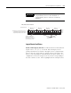
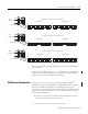
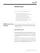
2-Slot
Addressing
Two slots are addressed as one logical group.
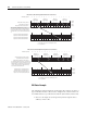
1-Slot
Addressing
One slot is addressed as one logical group.
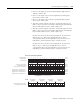
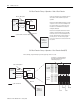
1/2-Slot
Addressing
One slot is addressed as two logical groups.
Slot 1
Slot 1
Slot 1Slot 2
Slot 1
Slot 1
Slot 1Slot 2
Input Image
Input Image
Input Image
Output Image
Output Image
Output Image
Remote Chassis
Remote Chassis
Remote Chassis
07815 07815
07815 07815
07815 07815
(1) The SLC 5/03 and SLC 5/04 processors cannot be programmed with the HHT.