
User guide

Publication 1747-UM013B-EN-P - January 2005
Scanner Configuration and Programming 4-31
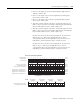
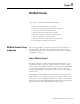
Retry Counter Example for Primary Devices
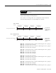
The scanner’s I/O image tables are configured as shown with M1
status files displaying the corresponding retry counters:
M1:e.16 - communication retry counter for RIO logical rack 0, group 0
M1:e.17 - not used in this example
M1:e.18 -communication retry counter for RIO logical rack 0, group 4
M1:e.19 - not used in this example
M1:e.20 - communication retry counter for RIO logical rack 1, group 0
M1:e.21 - not used in this example
M1:e.22 - not used in this example
M1:e.23 - not used in this example
M1:e.24 - not used in this example
M1:e.25 - communication retry counter for RIO logical rack 2, group 2
M1:e.26 - not used in this example
M1:e.27 - not used in this example
M1:e.28 - communication retry counter for RIO logical rack 3, group 0
M1:e.29 - not used in this example
M1:e.30 - not used in this example
M1:e.31 - communication retry counter for RIO logical rack 3, group 6
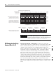
IMPORTANT
Your SLC control program cannot initialize/clear retry
counters.
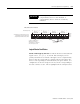
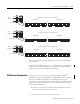
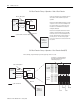
0
0123456789101112131415
101100001001001
Bit Number
Primary Logical Device Address, Word 1
G File - P rimary
Specifies RIO
addresses for
primary logical
devices.
RIO Logical Rack 0
Starting Group
6 4 2 0 6 4 2 0 6 4 2 0 6 4 2 0
RIO Logical Rack 1
Starting Group
RIO Logical Rack 2
Starting Group
RIO Logical Rack 3
Starting Group
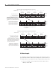
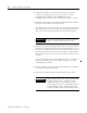
0
0123456789101112131415
100100010001100
Bit Number
Complementary Logical Device Address,
Word 3
G File - Comp lementary
Specifies RIO
addresses for
complementary
devices.
RIO Logical Rack 8
Starting Group
6 4 2 0 6 4 2 0 6 4 2 0 6 4 2 0
RIO Logical Rack 9
Starting Group
RIO Logical Rack 10
Starting Group
RIO Logical Rack 1 1
Starting Group