
User guide

Publication 1747-UM013B-EN-P - January 2005
Scanner Configuration and Programming 4-27
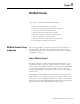
Logical Device Fault Status
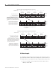
Words 12 through 15, bits 0 to 7 - indicate the device fault status for
logical racks 0, 1, 2, 3, 8, 9, 10, and 11. Bits 0 through 3 are for
primary/normal devices and bits 4 through 7 are for complementary
devices. Each bit corresponds to a quarter logical rack location. If a
device is not responding to communications, has gone off line, or is
configured to an incorrect logical rack size, all bits corresponding to
the device will be set to 1. This is highlighted in the example below.
IMPORTANT
When a primary device is inhibited, its
complementary device is also inhibited. A
complementary device cannot be exclusively
inhibited.
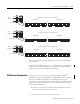
0
RIO Rack 8
Starting Group
0246
RIO Rack 9
Starting Group
0246
RIO Rack 10
Starting Group
0246
RIO Rack 1 1
Starting Group
0246
0123456789101112131415
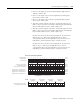
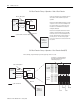
M1 File
Complementary Logical Device Address, Word 3
M1:e.3
Complementary Logical Image Size, Word 4
M1:e.4
Complementary Active Device Status, Word 5
M1:e.5
1 100100001000100
101111101100111
1001100001000000
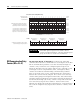
A 0 indicates that the device is
inhibited, not responding to
communications, or configured to
an incorrect logical rack size.
M1 (Status) File - W ord 5
Bit Number (decimal)
A 1 indicates that the configured
device is active.