
User guide


Publication 1747-UM013B-EN-P - January 2005
3-2 Installation and Wiring
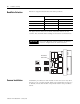
Baud Rate Selection
Below are supported baud rates and switch positions:
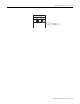
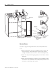
The figure below shows the location of the DIP switches on the
scanner. Also, the DIP switch settings are shown for each baud rate.
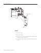
Scanner Installation
Installation procedures for this module are the same as for any other
discrete I/O or specialty module. Refer to the illustration on page 2-4
to identify chassis and module components listed in the procedures
below.
Baud Rate DIP Switch Position
Switch 1 Switch 2
57.6K baud on on
115.2K baud on off
230.4K baud off on
230.4K baud off off
IMPORTANT
For proper RIO link system operation, all devices
must be configured for the same baud rate.
Baud Rate
DIP Switch
57.6K baud 115.2K baud
230.4K baud 230.4K baud
12
N
O
12
N
O
12
N
O
12
N
O