
User guide

Publication 1747-UM013B-EN-P - January 2005
1-16 Overview
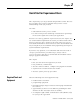
012 3 45678
Slot Pair
1234
IIII
OOOO
012 3 45678
Slot Pair
1234
OOOO
O
I = Input Module
= Output Module
Input Image Output Image
= unused image space
Slot 1
Slot 2
Slot 3
Slot 4
Slot 5
Slot 6
Slot 7
Slot 8
Slot 1
Slot 2
Slot 3
Slot 4
Slot 5
Slot 6
Slot 7
Slot 8
1
Slot Pair
2
3
4
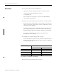
Slot 1
Slot 2
Slot 3
Slot 4
Slot 5
Slot 6
Slot 7
Slot 8
Slot 1
Slot 2
Slot 3
Slot 4
Slot 5
Slot 6
Slot 7
Slot 8
1
2
3
4
Input Image
from Primary Chassis
Output Image
from Primary Chassis
Output Image
from Complementary Chassis
Slot 1
Slot 2
Slot 3
Slot 4
Slot 5
Slot 6
Slot 8
Slot 1
Slot 2
Slot 3
Slot 4
Slot 5
Slot 6
Slot 8
Slot 1
Slot 2
Slot 3
Slot 4
Slot 5
Slot 6
Slot 7
Slot 8
Slot 1
Slot 2
Slot 3
Slot 4
Slot 5
Slot 6
Slot 7
Slot 8
Slot 7
Slot 7
Input Image
from Complementary Chassis
Slot Slot
Primary Chassis
Complementary Chassis
Slot 1
Slot 2
Slot 3
Slot 4
Slot 5
Slot 6
Slot 7
Slot 8
Slot 1
Slot 2
Slot 3
Slot 4
Slot 5
Slot 6
Slot 7
Slot 8
1
2
3
4
Slot 1
Slot 2
Slot 3
Slot 4
Slot 5
Slot 6
Slot 7
Slot 8
Slot 1
Slot 2
Slot 3
Slot 4
Slot 5
Slot 6
Slot 7
Slot 8
1
2
3
4
Slot 1
Slot 2
Slot 3
Slot 4
Slot 5
Slot 6
Slot 8
Slot 1
Slot 2
Slot 3
Slot 4
Slot 5
Slot 6
Slot 8
Slot 1
Slot 2
Slot 3
Slot 4
Slot 5
Slot 6
Slot 7
Slot 8
Slot 1
Slot 2
Slot 3
Slot 4
Slot 5
Slot 6
Slot 7
Slot 8
Slot 7
Slot 7
Primary Chassis I/O Image Complementary Chassis I/O Image
Scanner's I/O Image
1
2
3
4
Slot 1
Slot 2
Slot 3
Slot 4
Slot 5
Slot 6
Slot 8
Slot 1
Slot 2
Slot 3
Slot 4
Slot 5
Slot 6
Slot 8
Slot 1
Slot 2
Slot 3
Slot 4
Slot 5
Slot 6
Slot 7
Slot 8
Slot 1
Slot 2
Slot 3
Slot 4
Slot 5
Slot 6
Slot 7
Slot 8
Slot 7
Slot 7
Slot 1
Slot 2
Slot 3
Slot 4
Slot 5
Slot 6
Slot 7
Slot 8
Slot 1
Slot 2
Slot 3
Slot 4
Slot 5
Slot 6
Slot 7
Slot 8
1
2
3
4
Slot 1
Slot 2
Slot 3
Slot 4
Slot 5
Slot 6
Slot 7
Slot 8
Slot 1
Slot 2
Slot 3
Slot 4
Slot 5
Slot 6
Slot 7
Slot 8
Group 0
Group 2
Group 4
Group 6
Group 1
Group 3
Group 5
Group 7
Group 0
Group 2
Group 4
Group 6
Group 1
Group 3
Group 5
Group 7
Both images are overlapped in the
scanner. The overlapped image
appears where the primary chassis
image is configured to reside.
In this case, the primary chassis
image is configured as starting
logical rack 0 and starting logical
group 0.
IIII
Primary Chassis Configured As:
Logical Rack Number 0
Logical Group Number 0
Image Size (logical groups) 16
Addressing Mode 1/2-slot
Primary/Complementary Primary
Complementary Chassis Configured As:
Logical Rack Number 8 (decimal)
Logical Group Number 0
Image Size (logical groups) 16
Addressing Mode 1/2-slot
Primary/Complementary Complementary
Logical
Rack 0
Logical
Rack 1
07815
701017
Decimal
Octal
07815
701017
Decimal
Octal
07815
701017
Decimal
Octal
07815
701017
Decimal
Octal
07815
701017
Decimal
Octal
07815
701017
Decimal
Octal
Slot Pair Slot Pair Slot Pair
Slot Pair Slot Pair