
User guide

Publication 1747-UM013B-EN-P - January 2005
Overview 1-13
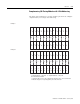
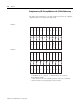
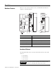
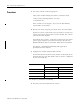
Complementary I/O: Placing Modules with 1-Slot Addressing
The figure below illustrates a possible module placement to configure
complementary I/O using 1-slot addressing.
I
16
E
M
P
T
Y
1
2
01234 5
Example 1
Example 2
I = Input Module (8- or 16-point) O = Output Module (8- or 16-point)
BT = Block Transfer Module
1 = Output modules use the same output image table bits. This is not recommended.
I
16
I
16
I
16
O
16
O
16
O
16
O
16
BT I
16
O
16
O
16
67 0 1 2 3
O
16
O
16
I
16
I
16
I
16
O
16
O
16
1
I
16
O
16
I
16
O
16
I
16
01234 5
I
16
I
16
67 0 1 2 3
O
16
O
16
I
16
I
16
I
16
I
16
I
16
I
16
I
16
I
16
I
16
O
16
O
16
O
16
O
16
O
16
O
16
O
16
O
16
O
16
O
16
2 = Must be empty if corresponding primary slot is block transfer..