Remote I/O Scanner 1747-SN User Manual
Important User Information Solid state equipment has operational characteristics differing from those of electromechanical equipment. Safety Guidelines for the Application, Installation and Maintenance of Solid State Controls (Publication SGI-1.1 available from your local Rockwell Automation sales office or online at http://www.ab.com/manuals/gi) describes some important differences between solid state equipment and hard-wired electromechanical devices.
Summary of Changes The information below summarizes the changes to this manual since the last printing. Updates to the manual include using RSLogix 500 instead of APS software. To help you find new and updated information in this release of the manual, we have included change bars as shown to the right of this paragraph. The table below lists the sections that document new features and additional or updated information on existing features.
Summary of Changes 2 Publication 1747-UM013B-EN-P - January 2005
Table of Contents Important User Information . . . . . . . . . . . . . . . . . . . . . . . . 1-2 Table of Contents Overview Chapter 1 System Overview . . . . . . . . . . . . . . . . . . . . . . . . . . . . . . . 1-1 Scanner I/O Image Division . . . . . . . . . . . . . . . . . . . . . 1-3 How the Scanner Scans Remote I/O . . . . . . . . . . . . . . . . . 1-4 SLC and Scanner Asynchronous Operation . . . . . . . . . . 1-4 How the Scanner Interacts with Adapters . . . . . . . . . . . . . .
Table of Contents 2 When Changing From Run Mode . . . . . . . . . . . . . . . . . 3-8 Status LEDs. . . . . . . . . . . . . . . . . . . . . . . . . . . . . . . . . . . . 3-9 Chapter 4 Scanner Configuration and Programming Understanding Remote Input and Output Image Files. . . . . 4-1 RIO Configuration Using G Files . . . . . . . . . . . . . . . . . . . . 4-4 Rules for Configuring the Scanner. . . . . . . . . . . . . . . . . 4-7 Considerations When Configuring Remote I/O . . . . . . . . . .
Table of Contents 3 Error Codes . . . . . . . . . . . . . . . . . . . . . . . . . . . . . . . . . . . 6-2 Retry Counters . . . . . . . . . . . . . . . . . . . . . . . . . . . . . . . . . 6-2 Block Transfers . . . . . . . . . . . . . . . . . . . . . . . . . . . . . . . . . 6-2 Appendix A Specifications Scanner Operating Specifications . . . . . . . . . . . . . . . . . . . . A-1 Network Specifications . . . . . . . . . . . . . . . . . . . . . . . . . . . A-1 Throughput Introduction . . . . . . . . . . . .
Table of Contents 4 Directional Non-Continuous Block Transfer Example Bidirectional Continuous Block Transfer Example . . . Bidirectional Alternating Block Transfer . . . . . . . . . . Bidirectional Alternating Repeating Block Transfer . . Glossary Index Publication 1747-UM013B-EN-P - January 2005 . . . . D-12 D-16 D-21 D-27 Rockwell Automation Support . . . . . . . . . . . . . . . . . . . . . . 1-7 Installation Assistance . . . . . . . . . . . . . . . . . . . . . . . . .
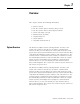
Chapter 1 Overview This chapter contains the following information: • • • • • • • • System Overview system overview how the scanner interacts with the SLC processor how the scanner interacts with adapter modules scanner I/O image concepts extended node capability complementary I/O scanner features compatible network devices The Remote I/O (RIO) Scanner, Catalog Number 1747-SN, is the remote I/O scanner for the SLC 500.
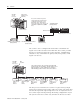
1-2 Overview RIO Scanner (Master of the RIO Link) SLC 5/02 or Later Processor The scanner transfers input and output data between itself and all configured network devices over twisted pair cable. Note that the end-to-end length of the cable can be a maximum of 3,048 meters (10,000 feet).
Overview 1-3 your application program requires. Configuration is done through the confiGuration file (G file). Refer to Chapter 4, Configuration and Programming, for more information. IMPORTANT The SLC 500 processor (SLC 5/02 or later) supports multiple scanners in its local I/O chassis.
1-4 Overview The scanner image contains the image of each adapter on the RIO link. The adapter is assigned a portion of the scanner image, which is referred to as the adapter image. How the Scanner Scans Remote I/O The scanner communicates with each logical device in a sequential fashion. First, the scanner initiates communication with a device by sending output data to the device. The device then responds by sending its input data back to the scanner, as illustrated below.
Overview 1-5 The figure below illustrates the asynchronous operation of the SLC processor and RIO scanner. SLC Processor Scan Cycle RIO Scanner Scan Cycle SLC Input Image File The SLC processor reads the scanner input image file into the SLC input image file, processes it, and creates an SLC output image file. The SLC processor transfers its output file to the scanner..
1-6 Overview Processor Scanner RIO Discrete Transfers with Adapter 1 SLC Local Chassis RIO Discrete Transfers with Adapter 2 PanelView Operator Terminal RIO Discrete Transfers with Adapter 3 RIO Discrete Transfers with Adapter 4 Scanner I/O Image Concepts RediPANEL The scanner’s I/O image consists of RIO logical racks and I/O groups. A full RIO logical rack consists of eight input image and eight output image words. (A word consists of 16 bits of data.
Overview 1-7 Input Image Half of a Scanner 's I/O Image Bit Number (decimal) RIO Logical Rack 0 RIO Logical Rack 1 RIO Logical Rack 2 RIO Logical Rack 3 Rack 0 Group 0 Word 0 Rack 0 Group 1 Word 1 Word 2 Rack 0 Group 2 Rack 0 Group 3 Word 3 Rack 0 Group 4 Word 4 Rack 0 Group 5 Rack 0 Group 6 Word 5 Word 6 Rack 0 Group 7 Word 7 Rack 1 Group 0 Word 8 Rack 1 Group 1 Word 9 Rack 1 Group 2 Word 10 Rack 1 Group 3 Word 11 Rack 1 Group 4 Word 12 Rack 1 Group 5 Word 13 Rack 1 Group 6 R
1-8 Overview SLC 5/02 or Later Processor RIO Scanner Device 2 Device 1 Device 3 Three-Quarter Logical Rack Device Begins at Logical Rack 1, Group 0. Full Logical Rack Device Begins at Logical Rack 0, Group 0. Device 4 Half Logical Rack Device Begins at Logical Rack 2, Group 0. Quarter Logical Rack Device Begins at Logical Rack 2, Group 4. Important: The illustration below shows only the scanner's input image. The output image looks the same.
Overview 1-9 Transferring Data with RIO Discrete and Block Transfers Input and output image data and command information are quickly exchanged between a scanner and adapter using RIO discrete transfers. RIO discrete transfers are the simplest and fastest way a scanner and adapter communicate with each other. RIO discrete transfers, which are transparent to the user, consist of the scanner sending the output image data to the adapter, and the adapter transmitting input data to the scanner.
1-10 Overview I/O is used. Refer to the following section for more information on complementary I/O. Complementary I/O Complementary I/O is very useful when portions of your input and output images are unused because it allows the images of two adapters to overlap each other in the scanner’s I/O image. To use complementary I/O, the I/O image from one adapter must be the mirror (complement) of the other.
Overview ATTENTION 1-11 If the logical rack numbers are not properly assigned, unpredictable operation of both ASB modules results. No ASB module errors occur. Refer to your ASB module user manual for specific information on setting the address of the complementary chassis. (For example, in the 1771-ASB manual the addresses for the complementary chassis are referred to as complementary chassis 0-3.
1-12 Overview Complementary I/O: Placing Modules with 2-Slot Addressing The following figures illustrate a possible module placement to configure complementary I/O using 2-slot addressing.
Overview 1-13 Complementary I/O: Placing Modules with 1-Slot Addressing The figure below illustrates a possible module placement to configure complementary I/O using 1-slot addressing.
1-14 Overview Complementary I/O: Placing Modules with 1/2-Slot Addressing The figure below illustrates a possible module placement to configure complementary I/O using 1-slot addressing.
Overview 1-15 Summary for Placing Modules Used In Complementary I/O Discrete Modules Addressing Method Types of Modules used Placement 2-slot 8-point Install input modules opposite output modules, and output modules opposite input modules.(1) 1-slot 8-point, 16-point 1/2-slot 8-point, 16-point, 32-point (1) If an input module resides in either slot associated with a logical group of the primary chassis, an input module cannot reside in that logical group’s complementary chassis.
1-16 Overview O I O I I O I O I O O I O I O I 3 7 I = Input Module O = Output Module Slot 0 Slot Pair 1 2 1 3 4 2 5 6 7 3 8 Slot 0 4 Slot Pair Primary Chassis I/O Image InputImage from Primary Chassis 10 8 Slot 1 Slot 1 Slot 2 Slot 2 Slot 3 Slot 3 Slot 4 Slot 4 Slot 5 Slot 5 Slot 6 Slot 6 Slot 7 Slot 7 Slot 8 Slot 8 4 5 2 6 3 8 4 Complementary Chassis Configured As: Logical Rack Number 8 (decimal) Logical Group Number 0 Image Size (logical groups) 16 Addressing Mode 1/2
Overview 1-17 Complementary I/O Application Considerations If you configure a complementary device to use more I/O image space than an associated primary device, then block transfers can only be performed to locations in the complementary device that have associated I/O image space in the primary device. For example, if a primary device is 1/2 logical rack and a complementary device is a full logical rack, block transfers can be performed only in the first 1/2 logical rack of the complementary device.
1-18 Overview Hardware Features Below are the scanner’s features. You can find LED information in Chapter 6, Troubleshooting. SCANNER CAT SER FAC ) SLC 500 Remote I/O Scanner SERIAL NO. COMM FAULT SW1 O 1 2 N UL / LISTED IND. CONT. EQ. FOR HAZ. LOC. A196 2 SA ) HOST FRN.: 1 2 ON ON KBAUD 57.6 ON OFF 115.2 OFF ON 230.4 OFF OFF 230.4 CONNECT ONE END OF CABLE SHIELD TO CHASSIS MOUNTING BOLT. REFER T O USER'S MANUAL. MAKE IN U.S.A. PLUG FRN.
Overview 1-19 LEDs Two LEDs allow you to monitor scanner and communication status. FAULT LED - allows you to monitor scanner status. This LED is red. The FAULT LED’s normal state is off; therefore, it is off whenever the scanner is operating properly. COMM LED - allows you to monitor communication with all configured devices. This LED is green and its normal state is on once the processor has entered Run mode. The LED is red if there is a communication problem.
1-20 Overview Catalog Number 1771-JAB (1) Device Comments Single Point I/O Adapter Module Single Point I/O Adapter Module 1771-DCM Direct Communication Module - 1778-ASB(1) Remote I/O Adapter Module - 1747-DCM(1) Direct Communication Module - 2706-xxxx(1)(5) DL40 Dataliner - 2705-xxx(1) RediPANEL Requires half logical rack configuration if you want to use stored messages.Requires half logical rack configuration if you want to use stored messages.
Chapter 2 Quick Start for Experienced Users This chapter helps you to get started using the RIO Scanner. We base the procedures here on the assumption that you have a basic understanding of SLC 500 products.
2-2 Quick Start for Experienced Users Procedures 1. Check the contents of the shipping box. Unpack the module making sure that the contents include: • RIO Scanner (Catalog Number 1747 SN) • termination kit If the contents are incomplete, call your local Allen-Bradley representative for assistance. 2. Ensure you chassis supports placement of the 1747-SN module. Review the power requirements of your system to see that your chassis supports placement of the scanner module.
Quick Start for Experienced Users ATTENTION 2-3 Never install, remove, or wire modules with power applied to the chassis or devices wired to the module. Make sure system power is off; then insert the scanner module into your 1746 chassis. In this example procedure, local slot 1 is selected. See Chapter 3, Installation and Wiring. Make sure system power is off; then insert the scanner module into your 1746 chassis. In this example procedure, local slot 1 is selected.
2-4 Quick Start for Experienced Users 7. Enter the number of scanned words. Enter the number of Scanned Input and Output Words using the Specialty I/O and Advanced Setup menus. The default value is 32 I/O words. You can specify less than 32 and reduce the processor scan time by transferring only the part of the input and output image that your application requires. It is important that you do not set either of these values to 0. If you do, the scanner will not work correctly.
Quick Start for Experienced Users 2-5 SCANNER COMM FAULT FAULT LED is off. COMM LED is green.
2-6 Quick Start for Experienced Users Publication 1747-UM013B-EN-P - January 2005
Chapter 3 Installation and Wiring This chapter contains the information necessary to: • • • • Compliance to European Union Directives select the baud rate insert the scanner into the SLC chassis wire the RIO link power up the scanner If this product has the CE mark, it is approved for installation within the European Union and EEA regions. It has been designed and tested to meet the following directives.
3-2 Installation and Wiring Baud Rate Selection Below are supported baud rates and switch positions: Baud Rate DIP Switch Position Switch 1 Switch 2 57.6K baud on on 115.2K baud on off 230.4K baud off on 230.4K baud off off The figure below shows the location of the DIP switches on the scanner. Also, the DIP switch settings are shown for each baud rate. For proper RIO link system operation, all devices must be configured for the same baud rate.
Installation and Wiring ATTENTION IMPORTANT IMPORTANT 3-3 Disconnect system power before attempting to install, remove, or wire the scanner. Make sure you have set the DIP switches properly before installing the scanner. Before installation, ensure that your modular SLC power supply has adequate reserve current capacity. The scanner requires 600 mA @ 5V dc. Insertion 1. Disconnect power. 2. Align the full-sized circuit board with the chassis card guides.
3-4 Installation and Wiring Module Release Card Guide Cable Tie Removal 1. Disconnect power. 2. Remove all cabling. 3. Press the releases at the top and bottom of the module and slide the module out of the chassis slot. 4. Cover all unused slots with the Card Slot Filler, Catalog Number 1746-N2.
Installation and Wiring RIO Link Wiring 3-5 The scanner is connected to other devices on the RIO link in a daisy chain (serial) configuration. There are no restrictions governing the space between each device, provided the maximum cable distance (Belden 9463) is not exceeded. A 1/2 watt terminating resistor (included with the module) must be attached across line 1 and line 2 of the connectors at each end (scanner and last physical device) of the RIO link.
3-6 Installation and Wiring Terminating Resistor Last Physical Device End RIO Scanner RIO Link Connector RIO Link Connector Terminating Resistor Scanner End LINE 1 _______ SHIELD _____ LINE 2 _______ Line 1 ± Blue Shield ± Shield Line 2 ± Clear Chassis Mounting Bracket Ring Lug Shield Drain Wire For Series A Shield Drain Wire For New Installations Scanner Retrofits Using Series B Scanners New Installations To ensure a proper earth ground of the cable shield, follow these steps: 1.
Installation and Wiring IMPORTANT 3-7 The RIO cable shield must be grounded at the scanner end only. For Series A Scanner Retrofits To eliminate the need to strip the cable back, follow these steps: 1. Attach the shield wire and a short piece of #20 AWG wire (dotted line) to the shield lug of the RIO Link Connector. 2. Attach the other end of the #20 AWG wire to the ring terminal lug. 3. Attach the ring terminal lug to a chassis mounting bracket.
3-8 Installation and Wiring 2. Make sure you have configured your SLC processor and downloaded an application program. (Refer to chapter 4.) 3. Make sure power is applied to all devices on the RIO link. Scanner Operation Below is a description of the scanner’s operation at power up, run mode, and when changing from run mode to program or test mode. At Power Up At power up, the scanner’s communication LED (green LED) is off until the SLC is changed to Run or Test mode.
Installation and Wiring IMPORTANT Status LEDs 3-9 If you are using Block Transfer (BT) functionality, BTs may not function on adapters in Hold Last State settings. Refer to each device’s user manual for information on BTs and Hold Last State settings. The scanner has two LEDs that indicate its operating status, FAULT and COMM. The FAULT LED indicates the scanner’s overall status. The COMM LED indicates the RIO link communication status.
3-10 Installation and Wiring Publication 1747-UM013B-EN-P - January 2005
Chapter 4 Scanner Configuration and Programming This chapter contains information necessary to: • • • • • Understanding Remote Input and Output Image Files 1 understand remote I/O image files understand RIO configuration using G files control and view RIO devices using the M0 and M1 files understand slot addressing quickly configure the RIO Scanner The SLC system allows you to assign up to 32 words of input and output image data to a scanner.
4-2 Scanner Configuration and Programming SN Series B Scanner (RIO Master) Scanner Input and Output Images Output Image Bit Number Octal17 Bit Number Decimal15 Logical Rack 0 Logical Rack 1 Logical Rack 2 Logical Rack 3 10 7 8 7 Word 0 Word 1 Word 2 Word 3 Word 4 Word 5 Word 6 Word 7 Word 8 Word 9 Word 10 Word 1 1 Word 12 Word 13 Word 14 Word 15 Word 16 Word 17 Word 18 Word 19 Word 20 Word 21 Word 22 Word 23 Word 24 Word 25 Word 26 Word 27 Word 28 Word 29 Word 30 Word 31 Input Image 0 0 Bit Numbe
Scanner Configuration and Programming 4-3 e = slot number of the SLC chassis containing the scanner Bit Number (decimal) Logical Rack 0 Group 0 Logical Rack 0 Group 1 Logical Rack 0 Logical Rack 0 Group 2 Logical Rack 0 Group 3 Logical Rack 0 Group 4 Logical Rack 0 Group 5 Logical Rack 0 Group 6 Logical Rack 0 Group 7 Logical Rack 1 Group 0 Logical Rack 1 Group 1 Logical Rack 1 13 12 11 10 9 8 7 6 5 4 3 2 1 0 Word 0 SLC Input File Address I:e.0 Word 1 I:e.1 Word 2 I:e.
4-4 Scanner Configuration and Programming RIO Configuration Using G Files When you program your SLC system you use the G file to configure the scanner’s I/O image file. Your scanner’s G file configuration is based on the devices that you have on the RIO link. G file configuration consists of setting logical device starting addresses and the logical device image size of each physical device/adapter with which the scanner communicates. For RSLogix 500 version 5.
Scanner Configuration and Programming 4-5 configuration. The G file consists of five words which are described below. Word 0 - contains scanner information for the SLC processor. Your programming device automatically sets up Word 0. Do not attempt to alter word 0. IMPORTANT The term “primary” is used in conjunction with the term “complementary,” when referring to a complementary I/O configuration.
4-6 Scanner Configuration and Programming Setting device addresses in word 3 of the G file configures the system to operate in the complementary I/O mode. Not setting device addresses in word 3 causes the system to operate only in the primary/normal mode. If you wish to operate in the complementary mode and you only have primary devices configured, word 3 of the G file must be set to a decimal “1,” and word 4 of the G file must be equal to zero.
Scanner Configuration and Programming 4-7 Rules for Configuring the Scanner General • The smallest portion of the scanner’s I/O image that can be allocated to a single RIO device is two logical groups (1/4 logical rack). • If a device is configured in word 1, there must be image allocated to it in word 2. This rule also applies to words 3 and 4 with the following exception: if word 3 = 1 and word 4 = 0, the complementary mode is selected even though no complementary devices are configured.
4-8 Scanner Configuration and Programming • If there is at least one primary device configured in G file words 1 and 2, words 3 and 4 can both be zero, or the G file size can be set to 3 (complementary mode not selected). • The starting group of the primary and complementary chassis should be the same if they share the same image space. If the starting group is not the same, the image of the complementary device must not “cross over” into the space of a primary device.
Scanner Configuration and Programming 4-9 G File Bit Number 15 14 13 12 11 10 9 8 7 6 5 4 3 2 1 0 I/O Mix, Word 0 0 0 1 0 0 0 0 0 0 0 1 0 0 0 0 0 RIO Logical Rack 2 Starting Logical Group RIO Logical Rack 3 Starting Logical Group Primary/Normal Logical Device Address, Word 1 Primary/Normal Logical Image Size, Word 2 4 2 0 6 4 2 0 6 4 2 0 6 4 2 0 1 0 1 0 0 0 0 1 1 0 0 0 0 0 1 0 6 1 RIO Rack 3 Image Size 4 2 0 0 1 0 6 0 RIO Rack 2 Ima
4-10 Scanner Configuration and Programming Illegal Configuration Examples Having a primary device configured at Logical Rack 1, Logical Group 2 (bit 5) would be illegal since this image space is already being used by a complementary device. Having a complementary device configured at Logical Rack 10, Logical Group 2 (bit 9) would also be illegal since this image space is already being used by a primary device.
Scanner Configuration and Programming 4-11 e = slot number of the SLC chassis containing the scanner Bit Number (decimal) Logical Rack 0 Group 0 Logical Rack 0 Group 1 Logical Rack 0 Group 2 Logical Logical Rack 0 Group 3 Rack 0 Logical Rack 0 Group 4 Logical Rack 0 Group 5 Logical Rack 0 Group 6 Logical Rack 0 Group 7 Logical Rack 1 Group 0 Logical Rack 1 Group 1 15 14 13 12 11 10 9 8 7 6 5 4 3 2 1 0 Word 0 SLC Input File Address I:e.0 Word 1 I:e.1 Word 2 I:e.2 Word 3 I:e.
4-12 Scanner Configuration and Programming e = slot number of the SLC chassis containing the scanner Bit Number (decimal) Logical Rack 8 Group 0 Logical Rack 8 Group 1 Logical Rack 8 Group 2 Logical Logical Rack 8 Group 3 Logical Rack 8 Group 4 Rack 8 Logical Rack 8 Group 5 Logical Rack 8 Group 6 Logical Rack 8 Group 7 Logical Rack 9 Group 0 Logical Rack 9 Group 1 Logical Rack 9 Group 2 15 14 13 12 11 10 9 8 7 6 5 4 3 2 1 0 Word 0 SLC Input File Address I:e.0 Word 1 I:e.
Scanner Configuration and Programming 4-13 • The address and size of the devices you list in the G file must match the settings of each RIO device. Crossing Logical Rack Boundaries You express remote I/O image boundaries in an even number of groups. For example, the 1747-ASB image can be any size from two logical groups up to 32 logical groups (four logical racks), in 2 logical group increments.
4-14 Scanner Configuration and Programming When the scanner image assigned to an adapter is more than one logical device, the scanner sees the single physical device as multiple logical devices on the RIO link. The scanner communicates with each logical device independently, even if the logical devices are all assigned to one adapter. If a physical device image is more than one logical device, the following is true: • The scanner does not update all of the adapter image at the same time.
Scanner Configuration and Programming 4-15 Appendix B. You can find M file information relating to Block Transfer operations in Chapter 5, Block Transfer. Rung 2:0 To decrease program scan time, copy the first four words of the M1 File to a binary file and use these addresses throughout the program to access block transfer done, error, data, etc. information without interrupting the program scan many times.
4-16 Scanner Configuration and Programming M0 Control File Description You can control the operation of individual devices on the RIO link with M0 word 8 through M0 word 27 (M0:e.8 through M0:e.27). Through your application program, you can use the M0 file to: • Device Inhibit - command the 1747-SN RIO Scanner to stop scanning an RIO device by using words 8 through 11. • Device Reset - command an RIO device’s outputs to reset while the SLC processor is in Run or Test mode by using words 16 through 19.
Scanner Configuration and Programming 4-17 M0 (Control) File - RIO Device Control Words 15 14 13 12 11 10 9 8 7 6 5 4 3 2 1 0 Logical Rack 0 Device Inhibit Word 8 x x x x x x x x x x x x 0 1 1 0 M0:e.8 Logical Rack 1 Device Inhibit Word 9 x x x x x x x x x x x x 0 0 0 0 M0:e.9 Logical Rack 2 Device Inhibit Word 10 x x x x x x x x x x x x 1 0 0 1 M0:e.
4-18 Scanner Configuration and Programming Default: When the processor enters the Run mode, the scanner automatically inhibits any device not configured in the G file (bit set to 1). Attempting to inhibit an unconfigured device has no effect.
Scanner Configuration and Programming 4-19 address will not force a reset. To remove the reset condition, reset the bit (corresponding to the device logical starting address) to 0. See the mode table on page 4-22. Default: The SLC processor resets all bits in this field to 0 when it enters Run or Test mode.
4-20 Scanner Configuration and Programming Setting the bit to 1 will command all outputs off (regardless of the device’s Hold Last State setting). Only the device’s logical starting address bit matters. Setting other bits has no effect. Bits 0 to 3 correspond to I/O group locations within logical racks 0, 1, 2, and 3. Default: When the processor enters Run or Test mode, the scanner sets the starting address bit of each device configured in the G file to 1.
Scanner Configuration and Programming Device Reset and Remote Output Reset Considerations 4-21 The 1747-SN Scanner Device Reset words (M0:e.16 to M0:e.19) and the Remote Output Reset words (M0:e.24 to M0:e.27) operate in conjunction with each RIO device to determine the state of that RIO device’s outputs. The output control information that the scanner sends to the RIO device depends on how you configure these bits.
4-22 Scanner Configuration and Programming Example 2 - Once the SLC processor is in Run mode, the bits in the Remote Output Reset word have no effect on the RIO link device’s outputs. Setting the appropriate bits in the Device Reset Word to 1 instructs the RIO link device to reset its outputs.
Scanner Configuration and Programming M1 Status File Description 4-23 M1 file words 0 through 47 contain the status of all devices on the scanner’s RIO link. M1 is a read only file; do not write to this file. Words 0 to 47 of the M1 file provide the following information: • Word 0 (M1:e.0) - general communication status (overall device fault and communications attempted) • Word 2 (M1:e.2) - RIO baud rate status • Word 3 (M1:e.3) - complementary device starting address status • Word 4 (M1:e.
4-24 Scanner Configuration and Programming Device Fault bit. If the Communications Attempted bit is 1, the Enabled Device Fault bit is valid. M1 (Status) File Word 0 Bit Number (decimal) 15 14 13 12 11 10 9 8 7 6 5 4 3 2 1 0 M1 File x x x x x x x x x x x x x x 1 1 M1:e.
Scanner Configuration and Programming 4-25 M1 (Status) File - W ord 8 Bit Number (decimal) 15 14 13 12 11 10 0 0 1 0 0 0 Primary Logical Device Address, Word 8 9 8 7 6 1 0 0 2 0 6 4 1 0 0 0 5 0 4 0 3 2 1 0 0 1 1 0 1 2 0 6 4 2 0 0 1 1 0 0 1 M1 File M1:e.
4-26 Scanner Configuration and Programming Word 4 - provides status/feedback of the logical device image size you configure in word 4 of the G file (complementary devices). A bit set to 1 shows the logical image size of each logical device. Writing to word M1 file word 4 will not alter the contents of the G file.
Scanner Configuration and Programming 4-27 When a primary device is inhibited, its complementary device is also inhibited. A complementary device cannot be exclusively inhibited.
4-28 Scanner Configuration and Programming M1 (Status) File Primary/Normal Device Fault Status Bit Number (decimal) 15 14 13 RIO Rack 3 Starting Group 4 2 12 11 0 6 10 9 RIO Rack 2 Starting Group 4 2 8 7 0 6 6 5 RIO Rack 1 Starting Group 4 2 4 3 0 6 2 1 0 RIO Rack 0 Starting Group 4 2 0 M1 File Primary Device Address, Word 8 0 0 1 0 0 0 1 0 0 0 0 1 1 0 0 1 M1:e.8 Primary Device Size, Word 9 1 1 1 0 0 1 1 0 1 1 1 1 1 0 0 1 M1:e.
Scanner Configuration and Programming 4-29 • M1:e.3 is an image of word 3 (complementary logical device address) of the G file. • M1:e.9 is an image/copy of word 2 (primary/normal logical device size) of the G file. • M1:e.4 is an image/copy of word 4 (complementary logical device size) of the G file. • The three quarter logical rack device located in logical rack 3 (M1:e.9/13) is not active. The fault is indicated by the Enabled Device Fault status bit, bit 0, word 0 (M1:e.0/0).
4-30 Scanner Configuration and Programming M1 (Status) File Complementary 15 14 13 12 11 10 9 8 7 6 5 4 3 2 1 0 Status Word, Word 0 x x x x x x x x x x x x x x 1 1 M1 File M1:e.0 Baud Rate, Word 2 x x x x x x x x x x x x x x 0 1 M1:e.2 Bit Number (decimal) RIO Logical Rack 1 1 RIO Logical Rack 10 RIO Logical Rack 9 RIO Logical Rack 8 Complementary Device Starting Address, Word 3 0 0 1 0 0 0 1 0 0 0 0 1 1 0 0 1 M1:e.
Scanner Configuration and Programming 4-31 Your SLC control program cannot initialize/clear retry counters.
4-32 Scanner Configuration and Programming M1:e.32 - communication retry counter for RIO logical rack 8, group 0 M1:e.33 - not used in this example M1:e.34 - not used in this example M1:e.35 - not used in this example M1:e.36 - communication retry counter for RIO logical rack 9, group 0 M1:e.37 - not used in this example M1:e.38 - not used in this example M1:e.39 - not used in this example M1:e.40 - communication retry counter for RIO logical rack 10, group 0 M1:e.41 - not used in this example M1:e.
Scanner Configuration and Programming 2-Slot Addressing Two slots are addressed as one logical group. Input Image Remote Chassis 4-33 15 Output Image 8 7 0 Slot 2 15 Slot 1 1-Slot Addressing 8 7 Slot 2 0 Slot 1 One slot is addressed as one logical group. Input Image 15 8 7 Output Image 0 15 8 7 0 Remote Chassis Slot 1 1/2-Slot Addressing Slot 1 One slot is addressed as two logical groups.
4-34 Scanner Configuration and Programming 2. Assign the scanner to a physical slot in the SLC processor’s chassis by selecting Scanner from the list. If the scanner selection is not available, select OTHER from the I/O Configuration Screen and enter the Code ID number: 13608. 3. Enter the number of Scanned Input and Output Words using the Specialty I/O and Advanced Setup menus. The default value is 32 I/O words.
Chapter 5 RIO Block Transfer This chapter contains the following information: • • • • • • • • RIO Block Transfer Theory of Operation RIO block transfer theory of operation RIO block transfer general functional overview scanner’s block transfer buffer layout detailed operation of RIO block transfer RIO block transfer application considerations steps for setting up a block transfer quick reference for using status and control bits block transfer control logic examples This section provides a conceptual
5-2 RIO Block Transfer RIO Block Transfer Theory of Operation - Path of Block Transfer Chassis Backplane SLC Processor (SLC 5/02 or above) Refer to the diagrams on the following pages for more details on BTR and BTW sequence of operation. RIO M Scanner Files Block Transfer Write (BTW) data travels from the SLC processor across the chassis backplane via the scanner’s M files. The scanner then sends the data across the RIO link to the adapter or intelligent I/O module.
RIO Block Transfer 5-3 The steps below detail a successful Block Transfer Read (BTR). 1. The M0 file contains BTR control information which controls (initiates) the scanner BTR operation. (Refer to the Block Transfer Buffer Layout section for details on control information.) 2. The SLC control program initiates a block transfer read by commanding the scanner to perform the read operation. The adapter/intelligent I/O module sends BTR data across the RIO link to the RIO scanner. 3.
5-4 RIO Block Transfer RIO Block Transfer Theory of Operation - Block Transfer Write (BTW) In this example, Logical Rack 3, Logical Group 7, Logical Slot 1 is used.
RIO Block Transfer Using Block Transfer Instructions (BTR and BTW) BTR Block Transfer Read Rack Group Slot Control Block Data File Buffer File Requested Word Count Transmitted Word Count BTW Block Transfer Write Rack Group Slot Control Block Data File Buffer File Requested Word Count Transmitted Word Count EN 0 0 0 N10:140 N21:100 M1:1.3200 0 0 DN ER EN 0 0 0 N10:10 N20:0 M0:1.
5-6 RIO Block Transfer Parameters for BTR and BTW The instructions have the following parameters: • Data File - The address in the SLC processor’s data file containing the BTW or BTR data. • BTR/BTW Buffer File - Block transfer buffer file address; i.e. M0: e.x00, where “e” is the slot number of the scanner and “x” is the buffer number. The range of the buffer number is from 1 to 32. Each BTR and BTW instruction uses both the M1 and M0 files for a specific buffer number.
RIO Block Transfer 5-7 . Table 5.1 Control Block Structure Word 0 15 14 13 12 EN ST DN ER 11 10 9 EW 8 7 6 TO RW Word 1 Requested word count Word 2 Transmitted word count/Error code 5 4 3 2 Rack 1 Group 0 Slot Control Status Bits To use the BTR and BTW instructions correctly, examine the instruction’s control and status bits stored in the control structure. These bits are mapped to bits in word 0 of the control block structure. Figure 5.
5-8 RIO Block Transfer Successful Block Transfer Read/Write The illustration on the previous page shows a successful BT operation. 1. The SLC control program copies new data to the data file (BTW only) and solves the BT rung true, which sets the enable (EN) bit. 2.
RIO Block Transfer 5-9 Table 5.2 Control and Status Bit Descriptions Control/Status Bit Description Enable EN (bit 15) Block Transfer Enabled - (EN = Enabled). The processor sets/resets this bit depending on the rung state (true/false). The processor sends the enable bit to the RIO scanner when the BTR/BTW instruction is scanned. If the BT is not waiting (EW set) and is not started (ST set), and the EN bit sees a false-to-true transition, the RIO scan triggers a BT.
5-10 RIO Block Transfer Transmitted Word Count/Error Code, Word 2 (DLEN) Transmitted Word Count is the status of the actual number of BTW words sent or the number of BTR words received. The processor uses this number to verify the transfer. This number should match the requested word count (unless the transmitted word count is zero). If these numbers do not match, the processor sets the ER bit (bit 12).
RIO Block Transfer 5-11 Instruction Operation 1. The scanner processes the BTR/BTW when it detects that the SLC control program rung, which contains the BTR/BTW, goes true. If the RIO scanner detects any problem at this point (such as invalid block transfer control field, or unconfigured device), the control structure word 2 fills with the error code and the ER bit (bit 12) is set. If no problems occur, the EW bit (bit 10) and ST bit (bit 14) are set in the control block.
5-12 RIO Block Transfer 5. When the RIO scanner detects that the EN bit cleared, it then clears the EW, ST and DN or ER bits, as well as the Transmitted Word Count/Error Code. This ensures that the status bits in the control block are not reflecting the results of the previous block transfer operation. IMPORTANT To prevent configuration conflicts, it is highly recommended that each M-file buffer (My:e.x00) should be used by only one block transfer instruction. Programming Examples Table 5.
RIO Block Transfer 5-13 Figure 5.2 Directional Figure 5.
5-14 RIO Block Transfer Figure 5.4 Directional Continuous Figure 5.
RIO Block Transfer 5-15 Figure 5.6 Bi-directional Alternating Figure 5.
5-16 RIO Block Transfer Comparison to the PLC-5 BTR and BTW Block Transfer Reads and Writes in SLC processors are quite similar to the instructions in the PLC-5. However, some differences exist between them, as shown in Table 5.5 on page 5-16. Table 5.5 Block Transfer Comparison SLC PLC-5 Control Block 3-element integer (N) type 5-element integer (N) type or 1-element block transfer (BT) type. EN (Enable Bit) Follow BT rung state. Gets set when BT rung goes true.
Chapter 6 Troubleshooting This chapter provides information for troubleshooting the RIO scanner. Troubleshooting The FAULT LED is off whenever the scanner is operating properly. The COMM LED state is valid only when the FAULT LED is off. When the scanner’s LEDs change state, use the following table to isolate the cause. FAULT LED (Red) COMM LED (Red/Green) LED Condition Problem Solution Error Code(1) FAULT LED flashing red G file is missing. Enter configuration information in G file.
6-2 Troubleshooting Error Codes The SLC processor reports error codes in word 6 of the SLC processor status file. Below are the format of the status word and applicable error codes. Slot Number 01H to 1EH Error Code 62H - G File is missing 63H - Invalid user configuration 64H - Duplicate node fault 68H to 6FH - Scanner hardware problem For a complete description of the error codes, refer to the user manual provided with your programming device.
Appendix A Specifications This appendix provides scanner and system specifications, as well as throughput information.
A-2 Specifications Table A.2 DIP Switch Position for Baud Rate Selection Baud Rate Throughput Introduction DIP Switch Position Switch 1 Switch 2 57.6K baud on on 115.2K baud on off 230.4K baud off on 230.4K baud off off RIO throughput is defined as the time between when an input event occurs at an I/O module in an RIO chassis to when an output event occurs at an I/O module within the same RIO chassis.
Specifications A-3 Processor Scan Scanner Scan ASB Backplane Scan Scanner Processor ASB Module I/O Module I/O Module RIO Scan SLC Local Chassis Outputs to Modules Remote Chassis Inputs from Modules Inputs to Modules RemoteExpansion Chassis Outputs from Modules Output Device Input Device When the SLC control program detects that the remote input has been turned on (via the scanner output image), it activates the remote output device (via the scanner output image).
A-4 Specifications To calculate Tdm-nbt throughput, substitute values for the variables in the formula above. Locate these values in the following documents: Variable Variable Description Location of Variable Tps The total processor scan time (ms) Measured or estimated TRIO The total RIO scan time (ms) see the section RIO Scan Time Calculation (TRIO) on page A-4 Tadp The adapter throughput delay. For a 1747-ASB, this is two ASB backplane scan times.
Specifications A-5 Example Discrete I/O Throughput without Block Transfers Present An SLC 5/03 is controlling an RIO link running at 115.2K baud that has the following adapters: • One 1747-ASB module is configured as a 1/2 logical rack starting at logical rack 0. I/O chassis slot 1 contains 1746-IB16, 16 point input module I/O chassis slot 2 contains 1746-OB16, 16 point output module • Two adapters are each configured as full logical racks (logical racks 1 and 2).
A-6 Specifications TRIO = 1(4.0 ms) + 2(5.5 ms) + 3(3.5 ms) TRIO = 25.5 ms 3. Find TSNo on page A-14 in the table TSNo without M0 File Writes (Normal Mode). For this example Tupd > Thold, and there are 4 logical racks configured. Therefore: TSNo = 7.0 ms 4. Substitute all the values for variables in the throughput formula and solve for throughput: T dm – nbt = 2T ps + 2T RIO + 2T bp + T SNo + T SNi + T id + T od Tdm-nbt = 2(25.0)+ 2(25.5) + 8.0 + 7.0 + 5.0 + 10.0 + 1.0 Tdm-nbt = 132.
Specifications A-7 Variable Variable Description Location of Variable Tps The total processor scan time (ms) Measured or estimated TRIO The total RIO scan time (ms) see the section RIO Scan Time Calculation (TRIO) on page A-4 Tbtx Additional time due to sending any BT data on the RIO link. see the section Determining Tbtx on page A-8 Tadp The adapter throughput delay. For a 1747-ASB, this is two ASB backplane scan times.
A-8 Specifications Number of Normal Mode Logical Racks All Baud Configured(1) Rates Complementary Mode 57.6K baud 115.2K baud 230.4K baud 1 Logical Rack 16.0 19.0 24.0 32.0 2 Logical Racks 19.0 23.0 27.0 36.0 3 Logical Racks 22.0 26.0 30.0 39.0 4 Logical Racks 25.0 28.0 34.0 42.0 (1) See page A-12 if you are not sure how to determine the number of logical racks configured.
Specifications A-9 Adapter #1 (1747-ASB module): • starting logical rack 0, logical group 0 • 12 logical groups (1 1/2 logical racks) • one 8 word and two 4 word BT write/read modules in logical rack 0 • one 2 word BT write/read module in logical rack 1 Adapter #2 (1771-ASB module): • starting logical rack 2, logical group 0 • 2 logical groups (1/4 logical rack) • one 64 word BT write/read module Adapter #3 (1771-ASB module): • starting logical rack 2, logical group 2 • 2 logical groups (1/4 logical rack)
A-10 Specifications Tdm-bt = 2(25.0) + 2TRIO + 2Tbtx + 9.0 + 22.0 + 5.0 + 10.0 + 1.0 2. Calculate the total RIO scan time (TRIO). Locate the baud rate (115.2K) and adapter size which is found in the table on page B-4. Multiply the RIO scan times listed under the 115.2K heading by the number of each different type of rack that you have. Add those number together. TRIO = Tadapter1 + Tadapter2 + Tadapter3 TRIO = 1(5.5) + 1(4.0) + 2(3.5) TRIO = 16.5 ms 3. Calculate the maximum Tri time for each logical rack.
Specifications A-11 shown on page, where a BT is retriggered automatically upon each completion. BT throughput is always slower than discrete data transfer.
A-12 Specifications Variable Variable Description Location of Variable TM0 Time to perform M0 file write to enable BT appendix B TSNo-bt Scanner Output Delay time with BTs present. There must be an output delay time added for each BT buffer that is being used since the scanner processes only one BT enable or disable every TSNo-bt (to minimize the impact on discrete I/O throughput).
Specifications A-13 RIO Scanner Output Delay Time (TSNo) Tables The tables provided in this section show the maximum scanner output delay time (TSNo) for specific applications.
A-14 Specifications number of logical devices on the RIO network affects only TRIO, and only affects TSNo when additional logical racks are used. When complementary mode is selected, the number of configured racks is also determined by the number of primary or complementary racks configured, but not by both. (The maximum number of configured racks is 4.) That is, if there is a primary rack configured with a corresponding complementary rack, that is considered one logical rack.
Specifications A-15 TSNo with M0 File Writes (No Block Transfers) Normal Mode(1) Number of Logical Racks Configured All Baud Rates TSNo if Tupd ≤ Thold Thold TSNo if Tupd>Thold 1 Logical Rack 8.0 6.0 4.5 2 Logical Rack 10.0 8.0 5.5 3 Logical Rack 12.0 10.0 7.0 4 Logical Rack 14.0 12.0 8.0 (1) All times shown are in milliseconds (ms). Complementary(1) (2) Number of Logical Racks Configured 57.6K baud 115.2K baud 230.
A-16 Specifications Publication 1747-UM013B-EN-P - January 2005
Appendix B M0 - M1 Files and G Files This appendix contains important information about M0-M1 files and G files. The information is general in nature and supplements specific information contained in earlier chapters of this manual. M0 - M1 Files M0 and M1 files are data files that reside in specialty I/O modules only. There is no image for these files in the processor memory. The application of these files depends on the function of the particular specialty I/O module.
B-2 M0 - M1 Files and G Files Addressing M0-M1 Files The addressing format for M0 and M1 files is below: Mf:e.s/b Where M = module f = file type (0 or 1) e = slot (1-30) s = word (0 to max.
M0 - M1 Files and G Files Mf:e.s ] [ b Mf:e.s ]/[ b Mf:e.s ( ) b Mf:e.s (L) b B-3 Mf:e.s (U) b f = file (0 or 1) When youWhen are monitoring ladder program the Runprogram or Test mode, theRun display does not showthe these you arethemonitoring the in ladder in the or Test mode, instructions as being true display when thedoes processor theminstructions as true. APS or HHT not evaluates show these as being true when the processor evaluates them as true.
B-4 M0 - M1 Files and G Files Transferring Data Between Processor Files and M0 or M1 Files The processor does not contain an image of the M0 or M1 file. As a result, you must edit and monitor M0 and M1 file data via instructions in your ladder program. For example, you can copy a block of data from a processor data file to an M0 or M1 data file or vice versa using the COP instruction in your ladder program. The COP instructions below copy data from a processor bit file and integer file to an M0 file.
M0 - M1 Files and G Files B-5 Processor Instruction Type Access Time per Bit Instruction or Word of Data Access Time per Multi-Word Instruction SLC 5.
B-6 M0 - M1 Files and G Files COP COPY FILE Source #B3:0 Dest #M0:1.0 Length 34 If you are using a SLC 5/02 Series B processor, add 1580 µs plus 670 µs per word of data addressed to the M0 or M1 file. As shown above, 34 words are copied from #B3:0 to M0:1.0. Therefore, this adds 24360 µs to the scan time of the COP instruction. If you are using a SLC 5/02 Series C processor, add 950 µs plus 400 µs per word. This adds 14550 µs to the scan time of the COP instruction.
M0 - M1 Files and G Files B-7 Minimizing the Scan Time You can keep the processor scan time to a minimum by economizing on the use of instructions addressing the M0 or M1 files. For example, XIC instruction M0:2.1/1 is used in rungs 1 and 2 of the figure below, adding approximately 2 ms to the scan time if you are using a SLC 5/02 Series B processor. 1 M0:2.1 ] [ 1 2 B3 ] [ 12 B3 ( ) 10 B3 ( ) 14 M0:2.1 ] [ 1 XIC instructions in rungs 1 and 2 are addressed to the M0 data file.
B-8 M0 - M1 Files and G Files Capturing M0-M1 File Data The first two ladder diagrams in the last section illustrate a technique allowing you to capture and use M0 or M1 data as it exists at a particular time. In the first figure, bit M0:2.1/1 could change state between rungs 1 and 2. This could interfere with the logic applied in rung 2. The second figure avoids the problem. If rung 1 is true, bit B3/10 captures this information and places it in rung 2.
M0 - M1 Files and G Files S:1 ] [ 15 M0:2.1 (U) 1 B3 ] [ M0:2.1 ( ) 1 0 B-9 This rung is true for the first scan after powerup to unlatch M0:2.1/1. M0:2.1 ] [ 1 G Files Some specialty I/O modules use G (confiGuration) files (indicated in the specific specialty I/O module user’s manual). These files can be thought of as the software equivalent of DIP switches. The content of G files is accessed and edited offline under the I/O Configuration function.
B-10 M0 - M1 Files and G Files Figure B.1 I/O Configuration Screen 2. Click the “Adv Config” button to access the next menu. You can edit the number of words in each category. Although, it is recommended to leave them at default values unless specific project considerations require changes. See Chapter 4 for more information on configuring the module. Figure B.
M0 - M1 Files and G Files B-11 3. Click “Edit G Data” to access the setup screen for the module. Figure 2.3 Scanner G File Configuration Options Once you understand how the modules map Remote I/O locations, this menu is used to set up the Scanner. First select a group number in a logical rack. Then select the type of addressing for that group, either ¼ rack, ½ rack ¾ rack of full rack.
B-12 M0 - M1 Files and G Files Figure 2.4 Rack Configurations Once you select the group and type of addressing, the I/O word layout for the group is shown.
M0 - M1 Files and G Files B-13 Figure 2.5 Example of a Half-Rack Addressing in Group 1 After all devices have been properly mapped, click OK and the G file is automatically configured. This procedure eliminates the bit by bit process needed to configure the G file with other programming tools.
B-14 M0 - M1 Files and G Files Editing G File Data Data in the G file must be edited according to your application and the requirements of the specialty I/O module. You edit the data offline under the I/O configuration function only.
C Appendix RIO Configuration Worksheet This appendix provides a worksheet to help you configure your RIO devices. Directions We recommend that you use a photocopy of the worksheet so you retain a blank worksheet for future applications.
C-2 RIO Configuration Worksheet SLC Processor Output Image SLC Processor Input Image High Byte Bit Number Logical Rack 0 Logical Rack 1 Logical Rack 2 Logical Rack 3 - Decimal 15 High Byte Low Byte 8 7 Group 0 Group 1 Group 2 Group 3 Group 4 Group 5 Group 6 Group 7 Group 0 Group 1 Group 2 Group 3 Group 4 Group 5 Group 6 Group 7 Group 0 Group 1 Group 2 Group 3 Group 4 Group 5 Group 6 Group 7 Group 0 Group 1 Group 2 Group 3 Group 4 Group 5 Group 6 Group 7 Bit Number 0 I:e.0 I:e.1 I:e.2 I:e.
Appendix D Block Transfer Examples for Earlier Processors BTR and BTW Control Logic Examples These BTR and BTW instructions are for SLC 5/03, SLC 5/04 and SLC 5/05 or earlier processors with OS302, OS401, OS501 series B or earlier operating systems. Block Transfer Read Control Logic Example Rung 2:0 CONFIGURE THE BTR OPERATION TYPE, LENGTH AND RIO ADDRESS AT POWER-UP. BIT B3:100/7 MUST BE SET PRIOR TO GOING TO RUN TO INDICATE A BTR OPERATION.
D-2 Block Transfer Examples for Earlier Processors Rung 2:3 WHEN A BTR SUCCESSFULLY COMPLETES, BUFFER THE BT DATA AND UNLATCH THE BT ENABLE BIT. ALSO, UNLATCH THE BTR PENDING BIT AND LATCH THE BIT THAT CONTINUES CHECKING THE BTR STATUS UNTIL THE SN MODULE TURNS OFF THE DONE BIT. | | | | | VIRTUAL | | BTR DONE | | BIT BTR DATA | | B3:0 +COP---------------+ | |----] [----------------------------------------------+-+COPY FILE +-+-| | 13 | |Source #M1:1.
Block Transfer Examples for Earlier Processors D-3 Rung 2:5 WHEN USER LOGIC INITIATES A NEW BTR, LATCH THE ENABLE BIT , AS LONG AS A BTR IS NOT IN PROGRESS. ALSO, LATCH THE BTR PENDING BIT , SO THE BTR STATUS FILE WILL BE READ BY THE LADDER PROGRAM. | | | | SERVICE | | USER LOGIC| | | THE BTR | | TO |VIRTUAL |VIRTUAL |VIRTUAL STATUS/ | | INITIATE A|BT ENABLE |BTR DONE |BTR ERROR BTR | | BTR |BIT |BIT |BIT PENDING | | I:2.
D-4 Block Transfer Examples for Earlier Processors Block Transfer Write Control Logic Example Rung 2:0 CONFIGURE THE BTW LENGTH AND RIO ADDRESS AT POWER-UP. ALSO, BE SURE THE BLOCK TRANSFER OPERATION BIT IS A ”0” INDICATING A BTW. ALL THESE PARAMETERS MUST BE ENTERED PRIOR TO PLACING THE PROCESSOR IN THE RUN MODE. | | | | | | | POWER-UP | | BIT | | S:1 +COP---------------+ | |----] [--------------------------------------------------+COPY FILE +-| | 15 |Source #B3:100| | | |Dest #M0:1.
Block Transfer Examples for Earlier Processors D-5 Rung 2:4 IF A BTW ERRORS, UNLATCH THE ENABLE BIT, THE BTW PENDING BIT AND BUFFER THE BTW ERROR CODE. ALSO, LATCH THE BIT THAT CONTINUES CHECKING THE BTW STATUS UNTIL THE SN MODULE TURNS OFF THE ERROR BIT.
D-6 Block Transfer Examples for Earlier Processors Rung 2:6 MOVE THE VIRTUAL CONTROL WORD TO THE M0 FILE FOR THE SN MODULE WHENEVER A TRANSITION OF THE BTW ENABLE BIT OCCURS. | | | | | VIRTUAL | | BTW ENABLE | | BIT | | B3:100 +MOV---------------+ | |-+----] [-----+------------------------------------------+MOVE +-| | | 15 | |Source B3:100| | | | | | 0000000000000000| | | | | |Dest M0:1.
Block Transfer Examples for Earlier Processors D-7 Rung 2:0 CONFIGURE THE BTR OPERATION TYPE, LENGTH AND RIO ADDRESS AT POWER-UP. BIT B3:100/7 MUST BE SET PRIOR TO GOING TO RUN TO INDICATE A BTR OPERATION. | | | | | | | POWER-UP BTR | | BIT CONTROL | | S:1 +COP---------------+ | |----] [--------------------------------------------------+COPY FILE +-| | 15 |Source #B3:100| | | |Dest #M0:1.
D-8 Block Transfer Examples for Earlier Processors Rung 2:3 WHEN A BTR SUCCESSFULLY COMPLETES, BUFFER THE BTR DATA AND UNLATCH THE BTR ENABLE BIT. ALSO, UNLATCH THE BTR PENDING BIT AND LATCH THE BIT THAT CONTINUES CHECKING THE BTR STATUS UNTIL THE SN TURNS OFF THE DONE BIT. | | | | | VIRTUAL | | BTR DONE | | BIT BTR DATA | | B3 +COP---------------+ | |----] [----------------------------------------------+-+COPY FILE +-+-| | 13 | |Source #M1:1.
Block Transfer Examples for Earlier Processors D-9 Rung 2:5 BLOCK TRANSFER READS WILL EXECUTE CONTINUOUSLY AS LONG AS THE BTR PRECONDITION BIT IS TRUE.
D-10 Block Transfer Examples for Earlier Processors Rung 2:0 CONFIGURE THE BTR OPERATION TYPE, LENGTH AND RIO ADDRESS AT POWER-UP. BIT B3:100/7 MUST BE SET PRIOR TO GOING TO RUN TO INDICATE A BTR OPERATION. | | | | | | | POWER-UP BTR | | BIT CONTROL | | S:1 +COP---------------+ | |----] [--------------------------------------------------+COPY FILE +-| | 15 |Source #B3:100| | | |Dest #M0:1.
Block Transfer Examples for Earlier Processors D-11 Rung 2:3 WHEN A BTR SUCCESSFULLY COMPLETES, BUFFER THE BTR DATA AND UNLATCH THE BTR ENABLE BIT. ALSO, UNLATCH THE BTR PENDING BIT AND LATCH THE BIT THAT CONTINUES CHECKING THE BTR STATUS UNTIL THE SN TURNS OFF THE DONE BIT. | | | | | VIRTUAL | | BTR DONE | | BIT BTR DATA | | B3 +COP---------------+ | |----] [----------------------------------------------+-+COPY FILE +-+-| | 13 | |Source #M1:1.
D-12 Block Transfer Examples for Earlier Processors Rung 2:5 BLOCK TRANSFER READS WILL REPEAT AS FAST AS POSSIBLE AS LONG AS THESE RUNGS ARE SCANNED.
Block Transfer Examples for Earlier Processors D-13 Rung 2:0 CONFIGURE THE BTR OPERATION TYPE, LENGTH AND RIO ADDRESS AT POWER-UP. BIT B3:100/7 MUST BE SET PRIOR TO GOING TO RUN TO INDICATE A BTR OPERATION. | | | | | | | POWER-UP BTR | | BIT CONTROL | | S:1 +COP---------------+ | |----] [--------------------------------------------------+COPY FILE +-| | 15 |Source #B3:100| | | |Dest #M0:1.
D-14 Block Transfer Examples for Earlier Processors Rung 2:3 WHEN A BTR SUCCESSFULLY COMPLETES, BUFFER THE BTR DATA AND UNLATCH THE BTR ENABLE BIT. ALSO, UNLATCH THE BTR PENDING BIT AND LATCH THE BIT THAT CONTINUES CHECKING THE BTR STATUS UNTIL THE SN TURNS OFF THE DONE BIT. | | | | | VIRTUAL | | BTR DONE | | BIT BTR DATA | | B3 +COP---------------+ | |----] [----------------------------------------------+-+COPY FILE +-+-| | 13 | |Source #M1:1.
Block Transfer Examples for Earlier Processors Rung 2:5 INITIATE A BTR FOR EACH FALSE-TO-TRUE TRANSITION OF THE USER INPUT. | USER LOGIC | | TO | | INITIATE A | | BTR | | I:2 B3 B3 | |----] [------[OSR]-------------------------------------------------------(L)--| | 0 82 83 | Rung 2:6 WHEN USER LOGIC INITIATES A NEW BTR, LATCH THE ENABLE BIT AS LONG AS A BTR IS NOT IN PROGRESS. ALSO, LATCH THE BTR PENDING BIT SO THE BTR STATUS FILE WILL BE READ BY THE LADDER PROGRAM.
D-16 Block Transfer Examples for Earlier Processors Bidirectional Continuous Block Transfer Example The following rungs demonstrate a bidirectional continuous block transfer. The BTR and BTW will each execute as fast as possible, continuously and independently of one another. Rung 2:0 CONFIGURE THE BT OPERATION TYPE, LENGTH AND RIO ADDRESS (R,G,S IN DECIMAL) AT POWER-UP. BIT N7:50/7 MUST BE SET TO A ”1” TO INDICATE A BTR AND BIT N7:53/7 MUST BE A LOGICAL ”0” TO INDICATE A BTW OPERATION.
Block Transfer Examples for Earlier Processors D-17 Rung 2:3 COPY THE BTW STATUS AREA TO AN INTEGER FILE ONLY WHEN A BTW IS IN PROGRESS. THIS STATUS DATA WILL THEN BE USED THROUGHOUT THE PROGRAM AND WILL LIMIT THE NUMBER OF M-FILE ACCESSES. | | | | | | | BTW BTW | | PENDING STATUS | | B3 +COP---------------+ | |-+----] [-----+------------------------------------------+COPY FILE +-| | | 1 | |Source #M1:1.
D-18 Block Transfer Examples for Earlier Processors Rung 2:5 WHEN A BTR SUCCESSFULLY COMPLETES, BUFFER THE BTR DATA AND UNLATCH BOTH THE BTR VIRTUAL ENABLE BIT AND THE BTR PENDING BIT. ALSO, LATCH THE BIT THAT CONTINUES CHECKING THE BTR STATUS UNTIL THE SN MODULE TURNS OFF THE DONE BIT. | | | | | VIRTUAL | | BTR DONE | | BIT BTR DATA | | N7:60 +COP---------------+ | |----] [----------------------------------------------+-+COPY FILE +-+-| | 13 | |Source #M1:1.
Block Transfer Examples for Earlier Processors D-19 Rung 2:7 WHEN A BTW SUCCESSFULLY COMPLETES, UNLATCH THE BTW ENABLE BIT AND THE BTW PENDING BIT TO COMPLETE A BTW SEQUENCE. ALSO, LATCH THE BIT THAT CONTINUES CHECKING THE BTW STATUS UNTIL THE SN MODULE TURNS THE DONE BIT OFF.
D-20 Block Transfer Examples for Earlier Processors Rung 2:9 THIS RUNG WILL EXECUTE BLOCK TRANSFER READS CONTINUOUSLY, AS FAST AS POSSIBLE.
Block Transfer Examples for Earlier Processors D-21 Rung 2:12 MOVE THE VIRTUAL BTW CONTROL WORD TO THE M0 FILE FOR THE SN MODULE WHILE A BTW IS IN PROGRESS, AND CONTINUE DOING SO UNTIL THE ENABLE, DONE AND ERROR BITS ARE ALL TURNED OFF, COMPLETING THE HAND-SHAKE PROCESS. | | | | | VIRTUAL BTW | | BTW ENABLE CONTROL | | BIT BITS | | N7:53 +MOV---------------+ | |-+----] [-----+------------------------------------------+MOVE +-| | | 15 | |Source N7:53| | | | | | 0| | | | | |Dest M0:1.
D-22 Block Transfer Examples for Earlier Processors Rung 2:0 CONFIGURE THE BT OPERATION TYPE, LENGTH, AND RIO ADDRESS (R,G,S IN DECIMAL) AT POWER-UP. N7:50/7 MUST BE SET TO A ”1” TO INDICATE A BTR AND N7:53/7 MUST BE A LOGICAL ”0” TO INDICATE A BTW OPERATION. | | | | | | | POWER-UP BTR | | BIT CONTROL | | S:1 +COP---------------+ | |----] [----------------------------------------------+-+COPY FILE +-+-| | 15 | |Source #N7:50| | | | | |Dest #M0:1.
Block Transfer Examples for Earlier Processors D-23 Rung 2:3 COPY THE BTW STATUS AREA TO AN INTEGER FILE ONLY WHEN A BTW IS IN PROGRESS. THIS STATUS DATA WILL THEN BE USED THROUGHOUT THE PROGRAM AND WILL LIMIT THE NUMBER OF M-FILE ACCESSES. | | | | | | | BTW BTW | | PENDING STATUS | | B3 +COP---------------+ | |-+----] [-----+------------------------------------------+COPY FILE +-| | | 1 | |Source #M1:1.
D-24 Block Transfer Examples for Earlier Processors Rung 2:6 WHEN A BTR UNSUCCESSFULLY COMPLETES, BUFFER THE BTR ERROR CODE AND UNLATCH THE BTR ENABLE BIT AND THE BTR PENDING BIT. ALSO, LATCH THE CHECK BTR STATUS BIT IN ORDER TO CONTINUE READING THE STATUS INFORMATION FROM THE SCANNER UNTIL IT TURNS THE ERROR BIT OFF, COMPLETING THE HAND-SHAKE PROCESS.
Block Transfer Examples for Earlier Processors D-25 Rung 2:8 THIS RUNG AND THE NEXT RUNG WILL TOGGLE BETWEEN EXECUTING A BTR AND A BTW WHILE THE USER SUPPLIED BT PRECONDITION BIT (B3:0/11 IS USED IN THIS EXAMPLE) IS TRUE.
D-26 Block Transfer Examples for Earlier Processors Rung 2:10 MOVE THE VIRTUAL BTR CONTROL WORD TO THE M0 FILE FOR THE SN MODULE WHILE A BTR IS IN PROGRESS, AND CONTINUE DOING SO UNTIL THE ENABLE, DONE AND ERROR BITS ARE ALL TURNED OFF. | | | | | VIRTUAL BTR | | BTR ENABLE CONTROL | | BIT BITS | | N7:50 +MOV---------------+ | |-+----] [-----+------------------------------------------+MOVE +-| | | 15 | |Source N7:50| | | | | | 0| | | | | |Dest M0:1.
Block Transfer Examples for Earlier Processors D-27 Bidirectional Alternating Repeating Block Transfer The following rungs demonstrate a bidirectional alternating repeating block transfer. Using these rungs ensures the block transfer requests are executed in the order in which they are sent to the queue. This example also ensures that the BTR and BTW repeatedly alternate. The XIO conditions prevent the BTR and BTW from queuing simultaneously. The BT’s continue as long as the ladder rungs are scanned.
D-28 Block Transfer Examples for Earlier Processors Rung 2:2 UNLATCH THE BIT THAT CONTINUES TO CHECK THE BTR STATUS. WHEN A BTR IS COMPLETE, THE DONE OR ERROR BIT IS SET. THE LADDER PROGRAM MUST THEN UNLATCH THE ENABLE BIT, THEN WAIT FOR THE SN MODULE TO TURN OFF THE DONE/ERROR BIT BEFORE ANOTHER BTR TO THE SAME M-FILE LOCATION CAN BE INITIATED. THIS IS ONE COMPLETE BTR CYCLE.
Block Transfer Examples for Earlier Processors D-29 Rung 2:5 WHEN A BTR SUCCESSFULLY COMPLETES, BUFFER THE BTR DATA AND UNLATCH BOTH THE BTR VIRTUAL ENABLE BIT AND THE BTR PENDING BIT. ALSO, LATCH THE BIT THAT CONTINUES CHECKING THE BTR STATUS UNTIL THE SN MODULE TURNS OFF THE DONE BIT. | | | | | VIRTUAL | | BTR DONE | | BIT BTR DATA | | N7:60 +COP---------------+ | |----] [----------------------------------------------+-+COPY FILE +-+-| | 13 | |Source #M1:1.
D-30 Block Transfer Examples for Earlier Processors Rung 2:7 WHEN A BTW SUCCESSFULLY OR UNSUCCESSFULLY COMPLETES, UNLATCH THE BTW ENABLE BIT AND THE BTW PENDING BIT TO COMPLETE A BTW SEQUENCE. ALSO, LATCH THE BIT THAT CONTINUES CHECKING THE BTW STATUS UNTIL THE SN MODULE TURNS THE DONE/ERROR BIT OFF. IN ADDITION, BUFFER THE BTW ERROR CODE IN CASE AN ERROR OCCURS.
Block Transfer Examples for Earlier Processors D-31 Rung 2:9 | | | | | | | | | | | VIRTUAL |VIRTUAL |VIRTUAL |VIRTUAL | | BTR ENABLE|BTW ENABLE|BTW DONE |BTW ERROR | | BIT |BIT |BIT |BIT BTW DATA | | N7:50 N7:53 N7:64 N7:64 +COP---------------+ | |----]/[--------]/[--------]/[--------]/[-------------+-+COPY FILE +-+-| | 15 15 13 12 | |Source #N7:10| | | | | |Dest #M0:1.
D-32 Block Transfer Examples for Earlier Processors Rung 2:11 MOVE THE VIRTUAL BTW CONTROL WORD TO THE M0 FILE FOR THE SN MODULE WHILE A BTR IS IN PROGRESS, AND CONTINUE DOING SO UNTIL THE ENABLE, DONE AND ERROR BITS ARE ALL TURNED OFF, COMPLETING THE HAND-SHAKE PROCESS. | | | | | VIRTUAL BTW | | BTW ENABLE CONTROL | | BIT WORD | | N7:53 +MOV---------------+ | |-+----] [-----+------------------------------------------+MOVE +-| | | 15 | |Source N7:53| | | | | | 0| | | | | |Dest M0:1.
Glossary The following terms are used throughout this manual. Refer to the Allen-Bradley Industrial Automation Glossary, Publication Number AG-7.1, for a complete guide to Allen-Bradley technical terms. Adapter Any physical device that is a slave on the RIO link. Adapter Image That portion of the scanner image assigned to an individual adapter. ASB Module The Catalog Number 1747-ASB, 1771-ASB, or 1794 - ASB Remote I/O Adapter Module. The ASB module is an adapter.
Glossary 2 Extended Node Capability Functionality that allows you to use an 82 Ohm termination resistor at both ends of the RIO link for all baud rates. This functionality also allows for up to 32 adapters to be connected to the RIO link. G file The SLC file used to configure the scanner. You enter configuration information into this file during SLC processor programming. This file is loaded to the scanner by the SLC processor upon entering run mode.
Glossary 3 Logical Slot A logical slot consists of one input and one output byte within a logical group. A byte consists of 8 bits, each bit represents one terminal on a discrete I/O module. M files The SLC M0 and M1 data files that reside in the scanner. M files contain RIO network status (M1) and control (M0) information. The contents of these files can be directly accessed by your application program. Also, the M files are used to control and monitor RIO block transfer operations.
Glossary 4 RIO Discrete Transfer The exchange of image data between the scanner and adapter. RIO discrete transfers occur continuously whenever the scanner and adapter are communicating on the RIO link. RIO Link An Allen-Bradley communication system supporting high-speed serial transfer of Remote I/O (RIO) control information. This link consists of one master and one or more slaves.
Index Numerics 1/2-slot addressing complementary I/O 1-14 1-slot addressing complementary I/O 1-13 2-slot addressing complementary I/O configuration 1-12 A active device status 4-26 adapter 1-4 interaction with scanner 1-5 adapter image 1-4 size of 4-13 addressing I/O modules 4-32 overview 4-32 B bits communication attempted 4-23 enable device fault 4-23 block transfer theory of operation 5-1 throughput A-11 block transfer read 5-1 block transfer write 5-1 BTR 5-1 BTW 5-1 C capturing M0-M1 file data B-8
2 Index fault LED 1-19 G G file 4-4 editing G file data B-14 word 0 4-5 word 1, primary logical device address 4-5 word 2, primary logical image size 4-5 word 3, secondary logical device address 4-5 word 4, secondary logical image size 4-5 getting started 2-1 guidelines complementary I/O configuration 1-11 H hardware features DIP switch 1-18 LEDs 1-18 RIO network connector 1-18 I I/O image description 4-2 logical racks, groups, words, bits 4-2 I/O image division scanner 1-3 I/O image files overview 4
Index N noise immunity A-1 O operation run mode 3-8 startup 3-8 operation modes changing 3-8 overview M files 4-14 P power consumption A-1 programming scanner 4-33 R rack boundaries crossing logical 4-13 remote I/O configuration considerations 4-12 remote output reset control 4-20 removing the scanner 3-4 required tools and equipment 2-1 retry counters 6-2 RIO baud rate status 4-24 RIO block transfer - what it is 5-1 RIO device reset control 4-18 RIO image files 4-1 RIO link physical and logical specifi
4 Index U understanding I/O image files 4-1 slot addressing 4-32 W word 0 G file 4-5 word 1, primary logical device address Publication 1747-UM013B-EN-P - January 2005 G file 4-5 word 2, primary logical image size G file 4-5 word 3, secondary logical device address G file 4-5 word 4, secondary logical image size G file 4-5 words 24 through 27 M0 file 4-19
Index 5 Publication 1747-UM013B-EN-P - January 2005
Rockwell Automation Support Rockwell Automation provides technical information on the web to assist you in using its products. At http://support.rockwellautomation.com, you can find technical manuals, a knowledge base of FAQs, technical and application notes, sample code and links to software service packs, and a MySupport feature that you can customize to make the best use of these tools.