Installation Instructions Remote I/O Scanner (Catalog Number 1747-SN) Inside ................................................................................................page For More Information ............................................................................... 2 Hazardous Location Considerations ........................................................ 3 Environnements dangereux ..................................................................... 3 Overview .............................
Remote I/O Scanner For More Information For Refer to this Document Pub. No. A more detailed description on how to install, configure, and operate your Remote I/O Scanner. Remote I/O Scanner User Manual 1747-6.6 A more detailed description on how to install and use your modular SLC 500 system SLC 500 Modular Hardware Style Installation and Operation Manual 1747-UM011 A reference manual that contains status file data and instruction set information for SLC 500 processors.
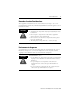
Remote I/O Scanner 3 Hazardous Location Considerations This equipment is suitable for use in Class I, Division 2, Groups A, B, C, D or non-hazardous locations only. The following WARNING statement applies to use in hazardous locations. WARNING ! EXPLOSION HAZARD • Substitution of components may impair suitability for Class I, Division 2. • Do not replace components or disconnect equipment unless power has been switched off. • Do not connect or disconnect components unless power has been switched off.
Remote I/O Scanner Overview The Remote I/O (RIO) Scanner, 1747-SN, enables communication between an SLC™ processor and remotely located 1746 I/O chassis and other RIO-compatible Allen-Bradley operator interface and control devices. The 1747-SN scanner communicates with remote devices using the A-B Remote I/O link. The RIO link consists of a single master (scanner) and multiple slaves (adapters). Communication between devices occurs over twisted-pair cable with the devices daisy-chained together.
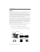
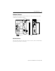
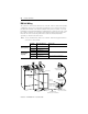
Remote I/O Scanner 5 Hardware Features The figure below shows the scanner’s features. RIO Link Connector, Status LED, and DIP Switch information follows. SCANNER CAT SER FAC SLC 500 Remote I/O Scanner SERIAL NO. Status LEDs SW1 O N 1 2 1 LISTED IND. CONT. EQ. ON ON OFF OFF 2 KBAUD ON OFF ON OFF 57.6 115.2 230.4 230.4 CONNECT ONE END OF CABLE SHIELD TO CHASSIS MOUNTING BOLT. REFER TO USERS MANUAL. HOST FRN MADE IN U.S.A.
Remote I/O Scanner Status LEDs The scanner has two LEDs, FAULT and COMM, which indicate its operating status. • FAULT LED - indicates the scanner’s overall status. The red FAULT LED is off whenever the scanner is configured and operating properly. • COMM LED - allows you to monitor communication with all configured devices. This LED is green once the scanner is in the Run mode. It is red if a hardware fault is detected. The COMM LED status information is valid only when the FAULT LED is off.
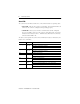
Remote I/O Scanner 7 Baud Rate DIP Switch The figure below shows the location of the DIP switch and the DIP switch settings for the supported baud rates. For proper system operation, the baud rate of all devices on the RIO link must be the same. IMPORTANT O N 12 57.6K baud O1 N 2 115.2K baud O N 12 230.4K baud O1 N 2 230.
Remote I/O Scanner Required Tools and Equipment Have the following tools and equipment ready: • medium blade screwdriver • termination kit (the package, containing resistors and a ring lug, which was included with the scanner) • approximately 38 cm (15 inches) of #20 AWG wire for grounding the drain shield to the SLC chassis (for Series A retrofits) • adequate length of RIO communication cable (Belden™ 9463) for your specific application Installation Make sure you have set the DIP switch properly befor
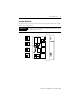
Remote I/O Scanner 9 1. Disconnect power. 2. Align the full-sized circuit board with the chassis card guides. The first slot (slot 0) of the first rack is reserved for the SLC 500 processor. 3. Slide the module into the chassis until the top and bottom latches catch. 4. Attach the RIO link cable to the connector on the front of the module, behind the door. Ground the cable’s shield wire to a chassis mounting bracket. Refer to the RIO link wiring illustration on page 10. 5.
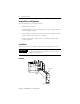
Remote I/O Scanner RIO Link Wiring The scanner is connected to other devices on the RIO link in a daisy-chain (serial) configuration. There are no restrictions governing the space between each device, provided the maximum cable distance (Belden 9463) is not exceeded. A 1/2 watt terminating resistor (included with the module) must be attached across line 1 and line 2 of the connectors at each end (scanner and last physical device) of the RIO link.
Remote I/O Scanner 11 For New Installations To ensure a proper earth ground of the cable shield, follow these steps: 1. While the RIO link connector is plugged into the scanner and lines 1 and 2 are connected, strip the cable back to expose enough shield drain wire to reach a chassis mounting bracket. 2. Attach the ring terminal lug (supplied) to the end of the shield drain wire. 3. Attach the ring terminal lug to the SLC chassis mounting bracket.
Specifications Backplane Current Compensation 600 mA at 5V dc Operating Temperature 0°C to +60°C (+32°F to +140°F) Storage Temperature -40°C to +85°C (-40°F to +185°F) Humidity 5 to 95% without condensation Noise Immunity NEMA Standard ICS 2-230 Agency Certification UL / C-UL listed Class I, Division 2, Groups A, B, C, D CE marked for all applicable directives C-Tick marked for all applicable acts Rockwell Automation, Allen-Bradley, SLC 500, PanelView, RediPANEL, Dataliner, and TechConnect are t