
User Manual Instruction Manual

Publication 1747-UM655B-EN-P - June 2007
36 Hardware Setup
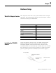
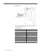
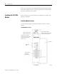
Dip Switch Setting
For the example application, we used the following configuration to
match the configuration of the SLC 500 processor’s RS-232 port
described in the previous section.
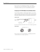
For this configuration, set the switches as shown in these tables.
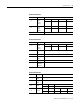
Channel 0 Configuration
Attribute Value
DF1 station address 0
Communication rate 19.2 Kbps
Full/Half-duplex Full-duplex
Parity None
Handshake No handshaking
Diagnostic command execution Disabled
Duplicate detect Enabled
Error detect CRC
Retries 3
DF1 ACK timeout 1.0 s
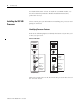
The upper position as shown above is
ON. The lower position is OFF.