
User Manual Instruction Manual

Publication 1747-UM655B-EN-P - June 2007
Before You Begin 19
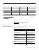
1747-SDN Module Data
Tables
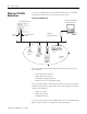
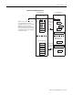
To manage the flow of data between your SLC 500 processor and the
network devices, the 1747-SDN module uses the following data tables:
• Scanner configuration table (SCT)
• Scanlist table (SLT)
• Device input data table
• Device output data table
• Device active table
• Device failure table
• Client/Server transaction tables
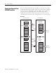
You can configure the first two of these data tables through
RSNetWorx for DeviceNet software.
• Scanner configuration table (SCT)
• Scanlist table (SLT)
These two tables are stored in the 1747-SDN module’s nonvolatile
memory and used to construct all other data tables.
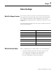
Scanner Configuration Table (SCT)
The SCT controls basic information your 1747-SDN module needs to
function on your DeviceNet network. It tells your 1747-SDN module:
• if it can transmit and receive input and output data.
• how long it waits after each scan before it scans the devices
again.
• when to send out its poll messages.
Scanlist Table (SLT)
The SLT supports I/O updating for each of your devices on the
network. It also makes it possible for your 1747-SDN module to make
device data available to your SLC processor. The SLT tells your
1747-SDN module:
• which device node addresses to scan.
• how to scan each device (strobe, poll, change of state, cyclic, or
any valid combination).
• how often to scan your devices.
• exactly where in each device’s total data to find the desired data.