
User Manual Instruction Manual

133 Publication 1747-UM655B-EN-P - June 2007
Appendix
D
Data Organization
Understand the Data
Organization of the Module
The module has four data areas to transfer data, status, and command
information between the module and the processor.
• SLC input image table
• SLC output image table
• SLC M1 file
• SLC M0 file
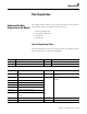
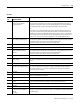
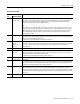
Input and Output Image Tables
The following table describes the mapping of the 1747-SDN input and
output image tables and the M1 and M0 files.
Words SLC Input Image Words SLC Output Image
0 Status 0 Command
1…31 DeviceNet Input Data (31 words) 1…31 DeviceNet Output Data (31 words)
Words SLC M1 File Words SLC M0 File
0…149 DeviceNet Input Data (150 words) 0…149 DeviceNet Output Data
(150 words)
150…205 Reserved (56 words) 150…223 Reserved
(74 words)
206…209 Device Active Table (4 words)
210 Node Address/Status Indicator (1 word)
211 Scan Counter (1 word)
212…215 Device Idle Table (4 words)
216…219 Device Failure Table (4 words)
220…223 Auto Verify Failure Table
(4 words)
224…255 Explicit Message Program Control (32 words) 224…255 Explicit Message Program Control (32 words)
256…394 Pass-through (139 words) 256…394 Pass-through (139 words)