
User Manual Instruction Manual

Publication 1747-UM655B-EN-P - June 2007
118 Data Map Example
Example Output Mapping
Scheme
This example’s output mapping scheme is a simplified and fixed map
of the discrete outputs and data from the device output data table to
DeviceNet devices.
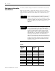
Devices present in the default database are strobed only; therefore,
the output data-map bits are mapped into each network’s strobe
message. If the discrete table is available, it serves as a source for the
strobe bits; otherwise, the source is found in M1/M0 file transfer
locations.
Example Characteristics
This example has the following characteristics:
• Strobe is used to send output to the DeviceNet devices.
• Poll is disabled.
• One output data bit each is sent to nodes 1…62.
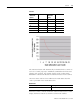
• The output data bits are embedded in the 8 byte (64 bit) data
portion of the DeviceNet strobe message.
• The output bit string source within the strobe message is divided
across the discrete outputs in the scanner’s discrete-output data
table.
Example Framework
This example adheres to the following structure:
• When a 1747-SDN module is running this configuration, there
cannot be any other 1747-SDN or 1771-SDN module on that
network.
• DeviceNet devices may reside only at nodes 1…62.
• Address 0 must be used for the scanner.
• The first word in the device output-image data table always
contains the module command word (this is applicable under
any mapping scheme).
• Output bits received from processor for nodes 1…62 are
mapped to the scanner’s discrete- output data table.
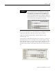
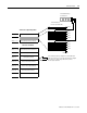
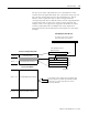
The following illustrates an output-data mapping scheme example for
the 1747-SDN module. Output bits are mapped from the processor’s
output image table, to the scanner’s output data table, and to each
device via strobe message.