747-SDN DeviceNet Scanner Module Catalog Number 1747-SDN, Series C User Manual
Important User Information Solid state equipment has operational characteristics differing from those of electromechanical equipment. Safety Guidelines for the Application, Installation and Maintenance of Solid State Controls (publication SGI-1.1 available from your local Rockwell Automation sales office or online at http://literature.rockwellautomation.com) describes some important differences between solid state equipment and hard-wired electromechanical devices.
Summary of Changes The information below summarizes the changes to this manual since the last publication. To help you find new and updated information in this release of the manual, we have included change bars as shown to the right of this paragraph. This manual contains this updated information.
Summary of Changes Publication 1747-UM655B-EN-P - June 2007
Table of Contents Preface Introduction . . . . . . . . . . . . . . . . . . . . . . . Audience . . . . . . . . . . . . . . . . . . . . . . . . . The Example Application . . . . . . . . . . . . . Common Techniques Used in This Manual. Additional Resources. . . . . . . . . . . . . . . . . . . . . . . . . . . . . . . . . . . . . . . . . . . . . . . . . . . . . . . . . . . . . . . . . . . . . . . . . . . . . . . . . . . 9 . 9 10 11 11 What This Chapter Contains . . . . . . . . . . . . .
Table of Contents Chapter 5 Communicating with the What This Chapter Contains . . . . . . . . . . . . . . . . . . . . . . . . 63 DeviceNet Network from Another Additional Resources. . . . . . . . . . . . . . . . . . . . . . . . . . . . . . 64 System Requirements . . . . . . . . . . . . . . . . . . . . . . . . . . . . . 64 Network Communicating with the DeviceNet Network via an Ethernet Network . . . . . . . . . . . . . . . . . . . . . . . . . . . . . .
Table of Contents 7 Appendix C 1747-SDN Module Firmware History Purpose . . . . . . . . . . . . . . . . . . . . . . . . . . . . Revision 8.002. . . . . . . . . . . . . . . . . . . . . . . . Revisions 7.005 and 7.006 Known Anomalies . Revision 6.002. . . . . . . . . . . . . . . . . . . . . . . . Revision 5.001. . . . . . . . . . . . . . . . . . . . . . . . Revision 4.026. . . . . . . . . . . . . . . . . . . . . . . . . . . . . . . . . . . . . . . . . . . . . . . . . . . . . . . . . . . . . . . . .
Table of Contents Publication 1747-UM655B-EN-P - June 2007
Preface Introduction This user manual is designed to provide you enough information to get a small example application up and running. Use this manual if you are knowledgeable about DeviceNet and SLC 500 products, but may not have used the products in conjunction. The information provided is a base; modify or expand the examples to suit your particular needs. The manual contains instructions on configuring a DeviceNet network by using RSLinx and RSNetWorx for DeviceNet software.
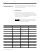
Preface The Example Application This manual describes how to set up an example application. The manual provides examples of each step of the setup, with references to other manuals for more details. System Components We used the following devices and software for the example application. For your own application, substitute your own devices to fit your needs. The recommended configurations in this user manual will help you set up the test system and get it working.
Preface Quantity Product Name Catalog Number Series/Revision 1 24V power supply Any regulated 24V dc, 8 A - 1 Personal computer IBM-compatible Pentium+ Windows 2000 or later - RSLogix 500 9324-RL0300xxx Rev 4.00 RSNetWorx for DeviceNet 9357-DNETL3 Rev 2.22 RSLinx 9355-WAB Rev 2.10 11 Software Common Techniques Used in This Manual The following conventions are used throughout this manual: • Bulleted lists provide information, not procedural steps.
Preface Resource ControlNet Coax Media Planning and Installation Guide, publication CNET-IN002 RediSTATION operator interface User Manual, publication 2705-UM001 SLC 500 Module Hardware Style User Manual, publication 1747-UM011 Quick Start for experienced Users, publication 1747-10.4 Description Provides information on planning and installing ControlNet coax media systems. Provides information on installing and using the RediSTATION operator interface.
Chapter 1 Before You Begin What This Chapter Contains This chapter provides an overview of communication between the SLC 500 processor and DeviceNet devices via the 1747-SDN module. The configuration data tables and the RSNetWorx for DeviceNet software dialogs and dialogs used to configure the data tables are also described. The following table identifies what this chapter contains and where to find specific information.
Before You Begin What Your 1747-SDN Module Does In a typical configuration, the 1747-SDN module acts as an interface between DeviceNet devices and the SLC 500 processor.
Before You Begin 15 Processor to I/O Input Read by Processor (Chapter 2) Configure SDN Module (Chapter 4) Computer Running RSNetWorx for DeviceNet Software Configure SDN Module (Chapter 4) Mapping Table (Chapters 2 and 4) Output Write by Processor (Chapter 2) Output Data to Devices from SDN (Chapter 2) Input Data from Device to SDN (Chapter 2) DeviceNet Network Input Device Output Device The 1747-SDN interface module can also be used to bridge a DeviceNet network with another network.
Before You Begin Communicating with Your Devices The 1747-SDN module communicates with a device via strobe, poll, change of state, and/or cyclic messages. It uses these messages to solicit data from or deliver data to each device. Data received from the devices, or input data, is organized by the 1747-SDN module and made available to the processor. Data received from your SLC 500 processor, or output data, is organized in the 1747-SDN module and sent on to your devices.
Before You Begin 17 Communicating With Other Devices 1747-SDN Module DeviceNet Devices Input Data From DeviceNet Devices Input Data Storage Different portions of data from a single device can be mapped to separate 1747-SDN memory locations. For example, On/Off values can be mapped to one location, diagnostic values to another. This is known as map segmenting. This concept is illustrated by byte A, stored separately as segments A1 and A2.
Before You Begin Communicating with Your SLC 500 Processor The 1747-SDN module does not send data to your processor. Data transferred between the module and the processor must be initiated by the processor. Output data is sent, or written, to the scanner by your processor by placing the data in the M0 file. This data is organized in the scanner, which in turn passes the data on to the scanned devices via strobe, poll, change of state, or cyclic messages.
Before You Begin 1747-SDN Module Data Tables 19 To manage the flow of data between your SLC 500 processor and the network devices, the 1747-SDN module uses the following data tables: • • • • • • • Scanner configuration table (SCT) Scanlist table (SLT) Device input data table Device output data table Device active table Device failure table Client/Server transaction tables You can configure the first two of these data tables through RSNetWorx for DeviceNet software.
Before You Begin • the size of the input data/output data. • exactly where to map the input or output data for your processor to read or write. • how your processor reads each device’s input data (M1/M0 file or discrete I/O).
Before You Begin 21 RSNetWorx for DeviceNet Configuration Dialog Map The main RSNetWorx for DeviceNet dialog. Click Online and select the driver to browse the network. Double-click the 1747-SDN icon to access the 1747-SDN Interface Module. Click the Scanlist tab to access the scanlist. Click Download to Scanner to download the scanlist. Select the Input tab and click AutoMap to automatically map input devices. Select the Output tab and click AutoMap to automatically map output devices.
Before You Begin What’s Next? The remaining sections of this manual provide the following information: • Chapter 2 covers the configuration process planning stage through a data mapping example. • Chapter 3 describes the hardware setup for the example application. • Chapter 4 covers configuration of the DeviceNet network by using RSNetWorx for DeviceNet software. • Chapter 5 describes how to configure a DeviceNet network from another network.
Chapter 2 Planning Your Configuration and Data Mapping Your Devices What This Chapter Contains What You Need to Know This chapter introduces questions you should ask before configuring your 1747-SDN communication module. In addition, it presents an example DeviceNet network and I/O data mapping scheme for a photoeye and a RediSTATION operator interface. The following table identifies what this chapter covers and where to find specific information.
Planning Your Configuration and Data Mapping Your Devices Beginning the Process Planning before configuring your 1747-SDN module helps you do these things: • • • • Use your memory and bandwidth efficiently Cater to device-specific needs and requirements Give priority to critical I/O transfers Leave room for expansion You need to know what is on your network. You should be familiar with each device’s: • communication requirements. • I/O importance and size. • frequency of message delivery.
Planning Your Configuration and Data Mapping Your Devices 25 Example Network Devices This example network has the following devices: • A computer running RSNetWorx for DeviceNet software • A 1747-SDN communication module interfacing an SLC 500 processor with the DeviceNet network • A Series 9000 photoelectric sensor (strobed) • A RediSTATION operator interface (polled) IMPORTANT In the following example, output is data sent to a device from a controller.
Planning Your Configuration and Data Mapping Your Devices RediSTATION Operator Interface Input and Output Data Mapping The RediSTATION operator interface has both inputs and outputs that must be mapped. The input byte is mapped to the 1747-SDN module’s M1 file and then to the SLC 500 processor’s input data file. The output byte is mapped to the 1747-SDN module’s M0 file and then to the SLC 500 processor’s output data file.
Planning Your Configuration and Data Mapping Your Devices 27 Mapping RediSTATION Input Data for an M1 File Data Table Read The following is an example of input data mapping for the RediSTATION operator interface. RediSTATION Input Byte What’s Happening? 1 byte 1 The bits for the RediSTATION operator interfaces’s red and green buttons are mapped into the 1747-SDN module’s M1 data table file.
Planning Your Configuration and Data Mapping Your Devices Mapping RediSTATION Output Data for an M0 File Data Table Write The RediSTATION operator interface’s output is mapped to the 1747-SDN module’s M0 file. Within the output byte is a bit for the indicator light. The output data file is then transferred from the SLC 500 processor application to turn the light on or off.
Planning Your Configuration and Data Mapping Your Devices 29 Photoeye Input Data Mapping The photoelectric sensor (photoeye) inputs are mapped to the 1747-SDN module’s M1 file and then to the SLC 500 processor’s input data file. The procedure for doing this by using RSNetWorx for DeviceNet software is described in chapter 4. The photoeye has no outputs to map. Series 9000 Photoeye Two input bits from the photoeye will be mapped: the status bit and the data bit.
Planning Your Configuration and Data Mapping Your Devices Mapping Photoeye Input Data for an M1 File Data Table Read 1 byte What’s Happening? 1 The status and data bits from the photoeye are mapped into the 1747-SDN Module’s M1 file data table. 2 S D = Unused Bits 1 The M1 file data table is then transferred to the SLC 500 processor’s input data file. Important: The 1747-SDN module only makes the data available for the processor to read.
Chapter 3 Hardware Setup What This Chapter Contains Installing the 1770-KFD Module This chapter describes how to set up the hardware for the example application. The following table describes what this chapter contains and where to find specific information.
Hardware Setup For detailed directions on how to install the 1770-KFD module, see the DeviceNet RS-232 Interface Module Installation Instructions, publication 1770-5.6. Installing the SLC 500 Processor These sections give you information on installing your processor and getting it connected. Identifying Processor Features Refer to the following figures to identify the features of your SLC 5/04 or SLC 5/05 processor.
Hardware Setup 33 Chassis Install IMPORTANT Insert the SLC 500 processor into the left slot (slot 0), as shown above. Remove the protective wrap after installing the processor. Establishing Data Highway Plus Communication For the examples using the Data Highway Plus (DH+) network in Chapters 5 and 6 of this manual, we installed a 1784-PKTX communication card in the host platform and an SLC 5/04 processor with these default Channel 1 DH+ configurations: • DH+ node address = 1 • Communication rate = 57.
Hardware Setup DH+ Network Connection Terminating Resistor See Chapter 5 for information on configuring the SLC 5/04 processor’s DH+ communication. Installing an Ethernet SLC 500 Processor (SLC 5/05 Processor) In order to communicate with your SLC 500 processor over an Ethernet network, you must install an Ethernet version of the processor (SLC 5/05 processor, catalog numbers 1747-L551, 1747-L552, or 1747-L553).
Hardware Setup 35 Configuring the RS-232 Port for the ControlNet Interface If you need to communicate with your SLC 500 processor via a ControlNet network, you must install a 1747-KFC15 ControlNet interface module in the chassis with your processor. You can use either a SLC 5/04 or a SLC 5/05 processor. The 1747-KFC15 module connects to the SLC 500 processor via the processor’s RS-232 port (channel 0).
Hardware Setup Dip Switch Setting The upper position as shown above is ON. The lower position is OFF. For the example application, we used the following configuration to match the configuration of the SLC 500 processor’s RS-232 port described in the previous section. Channel 0 Configuration Attribute Value DF1 station address 0 Communication rate 19.
Hardware Setup 37 Bank S1 DIP Switches Switch Setting Position Switches 1…3 Upper digit of DF1 station address SW1 SW2 SW3 Digit ON ON ON 0 Switches 4…6 Lower digit of DF1 station address SW4 SW5 SW6 Digit ON ON ON 0 Switches 7…8 Both OFF Bank S2 DIP Switches Switch Setting Position Switches 1…3 Upper digit of DF1 station address SW1 SW2 SW3 Digit ON OFF OFF 19200 Switch 4 Full/Half-dup OFF = Full-duplex lex Switch 5 Parity OFF = No parity Switch 6 Odd/even pari
Hardware Setup Refer to the SLC 500 ControlNet RS-232 Interface User Manual, publication 1747-5.34, for information on setting and verifying the 1747-KFC15 and SLC 500 processor communication parameters. Configuring the 1747-KFC15 Module’s ControlNet Node Address The 1747-KFC15 modules’s ControlNet node address is set by rotary switches S4 and S5 on the top of the module. Switch S5 sets the upper digit of the address and S4 the lower.
Hardware Setup 39 Install the 1747-KFC15 Module in the Chassis ATTENTION Electrostatic discharge can damage semiconductor devices inside the 1747-KFC15 module. To guard against electrostatic damage, wear an approved wrist strap grounding device, or touch a grounded object to rid yourself of electrostatic charge before handling the products. 1. Remove power from your 1746 I/O chassis. 2. Install the 1747-KFC15 module into an empty I/O slot.
Hardware Setup Refer to the ControlNet Coax Media Planning and Installation Guide, publication CNET-IN002, for complete instructions on connecting the tap to the ControlNet cable system. Installing the 1747-SDN Module These sections give you information on installing your module and getting it connected. Identifying Module Features Use the following figure to identify the features of the 1747-SDN module. 1747-SDN Module Features Module Status Indicator indicates module status.
Hardware Setup 41 Install the 1747-SDN Module In the Chassis ATTENTION Do not install the 1747-SDN module with the chassis power supply on. Installing the module with the chassis power supply on may damage the module. Follow these steps to install your module into the chassis. 1. Turn off the chassis power supply. 2. Select a slot for the module in the chassis. You may use any slot except the leftmost slot, which is reserved for the SLC 500 processor. 3.
Hardware Setup Connect the 1747-SDN Module to the DeviceNet Network Follow these steps to connect your module to the DeviceNet network. 1. Turn off the network power supply. ATTENTION Do not wire the 1747-SDN module with the network power supply on. Wiring the module with the network power supply on may short your network or disrupt communication. 2. Connect the DeviceNet drop line to the 10-pin linear plug. Match the wire insulation colors to the colors shown on the label.
Hardware Setup TIP 43 You use RSNetWorx for DeviceNet software to configure the module’s DeviceNet address and communication rate, if needed. This is done when configuring the DeviceNet network. See page 52. For additional information about installing the 1747-SDN module, see the 1747-SDN DeviceNet Scanner Module Installation Instructions, publication 1747-IN058.
Hardware Setup See Chapter 2 of the RediSTATION Operator Interface User Manual, publication 2705-UM001, for complete information about setting the DIP switches to configure the node address, data rate, output flash rate, and output fault state. Refer to the following illustration as you connect the RediSTATION operator interface to the network. TIP You do not need to disconnect incoming power from the DeviceNet network before connecting the RediSTATION operator interface.
Hardware Setup 45 Top View of Series 9000 Photoeye Programming Pushbutton Sensitivity Adjustment Yellow - Output Green - Margin Red/Green - Status For detailed directions, see the instructions that came with your photoeye. How Your Network Will Look When you have finished installing all the devices, the network should look similar to this. Typical Network Computer running Windows 2000 or later operating system, containing RSNetWorx for DeviceNet software.
Hardware Setup IMPORTANT What’s Next? Publication 1747-UM655B-EN-P - June 2007 Make sure each end of the DeviceNet trunk cable is properly terminated with a resistor. Refer to the DeviceNet Media Design and Installation Guide, publication DNET-UM072, for information. The next step is to configure the 1747-SDN module and perform I/O data mapping through RSNetWorx for DeviceNet software.
Chapter 4 Configuring the DeviceNet Network What This Chapter Contains Installing the Software This chapter describes how to configure the DeviceNet network by using RSLinx and RSNetWorx for DeviceNet software.
Configuring the DeviceNet Network Use RSLinx Software to Configure the DeviceNet Driver Follow these steps to configure your DeviceNet driver. 1. Start RSLinx software. The RSLinx main dialog opens. 2. Select Configure Drivers from the Communication menu. The following dialog appears. 3. Select DeviceNet Drivers from the above pull-down menu and click Add/New. You see the following choices.
Configuring the DeviceNet Network 49 4. Select the Allen-Bradley 1770-KFD driver. The Driver Configuration dialog appears. TIP Your driver setup depends on your particular system setup (COM port, communication rate, node address). Choose the appropriate settings for your system. 5. Configure the driver by using the example above as a guide and click on OK. The software takes a few seconds to configure the driver. When it is done the following prompt appears. 6.
Configuring the DeviceNet Network Using RSNetWorx for DeviceNet Software to Configure the 1747-SDN Module Scanlist Use RSNetWorx for DeviceNet software to do the following tasks: • • • • Set up an online connection Set the 1747-SDN node address Configure the I/O devices Download and save your configuration Set Up an Online Connection Follow these steps to set up an online connection to the DeviceNet network by using the 1770-KFD driver. 1. Start RSNetWorx for DeviceNet software.
Configuring the DeviceNet Network 4. Click Online 51 on the toolbar. A list of the available drivers in RSLinx software appears. Your list may appear different from that shown below, depending upon the drivers you have configured on your system. 5. Select the 1770-KFD-1, DeviceNet driver and click OK. You are prompted to upload or download devices before going online.
Configuring the DeviceNet Network 6. Click OK to upload the devices and go online. RSNetWorx for DeviceNet software begins browsing for network devices. When the software is done browsing, the network displayed on your screen should appear similar to the one shown below. TIP RSNetWorx for DeviceNet software performs a one-shot browse when you go online or choose the browse feature. The software polls for devices one time and displays the results.
Configuring the DeviceNet Network 53 If 00 appears to the right of the 1747-SDN icon and you do not need to change the node address or baud rate of any device, skip the remainder of this section and go to Configure the I/O Devices on page 55. IMPORTANT The network must not be active when performing node commissioning on the 1747-SDN module. Make sure the processor is in Program mode. (Note that this applies only to the 1747-SDN module. You may commission other devices with the processor in Run mode.
Configuring the DeviceNet Network 3. Select the 1770-KFD driver. The devices on the network appear in the right panel of the dialog. 4. Select the device you are commissioning in the right panel and click OK. The Node Commissioning dialog appears with the current settings for your 1747-SDN module. Your dialog should look similar to the one shown below. 5. Enter a 0 in the New Device Settings: Node Address box. 6. Click Apply and exit the dialog.
Configuring the DeviceNet Network 55 Configure the I/O Devices Follow these steps to configure the I/O devices. 1. Double-click the 1747-SDN module icon. The following dialog appears. 2. Click the Module tab. You receive the following prompt.
Configuring the DeviceNet Network 3. Click Upload. After uploading, the following dialog appears. 4. Verify the 1747-SDN module slot number is correct for your system. We used slot 2. TIP We used the Module Defaults for the other settings. For an explanation of these settings click Help. 5. Select the Scanlist tab. 6. Verify that the Automap on Add box is not checked.
Configuring the DeviceNet Network 57 7. Click the double arrow to add the photoeye and RediSTATION operator interface to the Scanlist. Verify the Photoeye Configuration 1. Double-click the photoeye in the Scanlist. The Edit I/O Parameters dialog appears for the photoeye. The I/O parameters define the configuration for the device in terms of how much and what data the device exchanges with the 1747-SDN module. By default, the photoeye will send 1 byte when it receives the strobe request. 2.
Configuring the DeviceNet Network The Edit I/O Parameters dialog appears for the RediSTATION operator interface. 2. Verify that the Polled box is checked and that the Rx Size and Tx Size are each 1 byte. 3. Click OK to close the Edit I/O Parameters dialog for the RediSTATION operator interface. 4. Click OK again. You are prompted to download the changes to the 1747-SDN module. 5. Click Yes to download the new configuration.
Configuring the DeviceNet Network 59 1. Double-click the 1747-SDN module icon and select the Input tab. 2. Select M File in the Memory field. 3. Highlight the RediSTATION operator interface and the photoeye and click AutoMap. The resulting device mapping appears in the lower panel. Photoeye inputs RediSTATION inputs In this example, the inputs from the RediSTATION operator interface appear in the M1 file for the device in slot 2 as word 0, bits 0…7.
Configuring the DeviceNet Network Recall from Chapter 2 that the START button is bit 1 and the STOP button is bit 0. Therefore, the addresses for the RediSTATION inputs are: START - M1:2.0.1 STOP - M1:2.0.0 The input from the photoeye appears in the M1 file for the device in slot 2 as word 0, bits 8…15. Recall from chapter 3 that the input bit is bit 0. Therefore, the address of the photoeye input is: M1:2.0.8 4. Note the addresses assigned to the START and STOP buttons and the photoeye in your system.
Configuring the DeviceNet Network 61 5. Select the Output tab. After mapping, the RediSTATION output address appears here. 6. Select M File in the Memory field. 7. Highlight the RediSTATION operator interface and click AutoMap. In this example, the output to the RediSTATION operator interface appears in the M0 file for the device in slot 2 as word 0, bits 0…7. Recall from Chapter 3 that the indicator light is output bit 0. Therefore, the address for the RediSTATION indicator light is: M0:2.0.0 8.
Configuring the DeviceNet Network Download and Save Your Configuration 1. Click the Scanlist tab and then Download to Scanner. 2. Select All Records. 3. Click Download to download the configuration to the 1747-SDN module. 4. Click OK to complete the DeviceNet scanner configuration. 5. From the File menu, choose Save As. 6. Save the configuration to a DeviceNet file. 7. Close the RSNetWorx for DeviceNet software.
Chapter 5 Communicating with the DeviceNet Network from Another Network What This Chapter Contains This chapter describes how to communicate with the DeviceNet network from another network, by using the SLC 500 pass-through feature. This feature can be used to adjust and fine tune the nodes on your network. Examples are provided for communicating from an Ethernet network and a Data Highway Plus network.
Communicating with the DeviceNet Network from Another Network Additional Resources These documents contain additional information on configuring other networks. Resource Description SLC Modular Style Hardware Installation and Operation Manual, publication 1747-UM011 Provides information about the Data Highway Plus network. Ethernet SLC 500 Processors Quick Start for Experienced Users, publication 1747-10.4 Provides information about the Ethernet interface. Comer, Douglas E.
Communicating with the DeviceNet Network from Another Network 65 The SLC 500 chassis used for these examples was set up with the following hardware mapping. The SLC 5/04 processor was used for the DH+ example. The SLC 5/05 processor was used for the Ethernet example. Hardware Mapping Communicating with the DeviceNet Network via an Ethernet Network Module Slot DH+ Address Ethernet Address DeviceNet Address SLC 500 5/04 Processor 0 1 - - SLC 500 5/05 Processor 0 - 130.130.130.
Communicating with the DeviceNet Network from Another Network Configure the Ethernet Devices Driver To communicate with your SLC 500 processor over the Ethernet network you must configure the Ethernet to SLC 500 driver. Follow these steps to configure the driver by using RSLinx software. 1. Start RSLinx software. 2. From the Communication menu, choose Configure Drivers. The Configure Drivers dialog appears. 3.
Communicating with the DeviceNet Network from Another Network 67 You are prompted to choose a name for the new driver. 4. Enter an appropriate driver name (for example, AB_ETH-1) and click OK. The Configure driver for Ethernet to PLC-5/SLC-5/5820-EI dialog opens. 5. Enter the IP address of the SLC 5/05 processor in the IP address or hostname field (130.130.130.2 in this example). IMPORTANT You must configure channel 0 of the SLC 5/05 processor with the same IP address you enter here.
Communicating with the DeviceNet Network from Another Network 6. Click Accept and then OK. The new driver is added to the list of Configured Drivers in RSLinx software. (Your list contains the drivers you have configured.) Configure the DeviceNet Network Pass-through Driver Before you can communicate with the 1747-SDN module via the Ethernet network, you must configure the DeviceNet pass-through driver (catalog number 1747-SDNPT) by using RSLinx software, version 2.10 or later.
Communicating with the DeviceNet Network from Another Network 69 2. From the Communication menu, choose Configure Driver. The Configure Drivers dialog appears. 3. From the Available Driver Types pull-down menu, select DeviceNet Drivers and click Add New. The following list of drivers appears. 4. Select the Allen-Bradley 1747-SDNPT driver. The Allen-Bradley 1747-SDNPT Driver Configuration dialog opens. 5.
Communicating with the DeviceNet Network from Another Network 8. Click OK. You are prompted to enter a name for the driver. 9. Enter an appropriate driver name (for example, 1747-SDNPT-2) and click OK. The new driver is added to the list of Configured Drivers in RSLinx software. (Your list contains the drivers you have configured for your system.) 10. Close or minimize RSLinx software.
Communicating with the DeviceNet Network from Another Network 71 1. Start RSNetWorx for DeviceNet software. 2. From the File menu, choose New. You may see the following dialog if you have the ControlNet network configured on your system. Otherwise, proceed to step 4. 3. Select DeviceNet Configuration and click OK. 4. Click Online on the toolbar.
Communicating with the DeviceNet Network from Another Network The Browse for network dialog appears. You see the drivers you have configured on your system. 5. Highlight 1747-SDNPT-2, DeviceNet driver and click OK. You receive the following prompt. 6. Click OK to upload the devices. RSNetWorx for DeviceNet software begins browsing for network devices.
Communicating with the DeviceNet Network from Another Network 73 You are now online to the DeviceNet network via the Ethernet network. See pages 55…62 of this manual for examples of how to use RSNetWorx for DeviceNet software to adjust network parameters. Communicate with the DeviceNet Network via a DH+ Network Before performing this example, the DH+ network must be configured and running. This example uses a SLC 5/04 processor.
Communicating with the DeviceNet Network from Another Network 2. From the Communication menu, choose Configure Drivers. The Configure Drivers dialog appears. 3. From the Available Driver Types pull-down menu, select DeviceNet Drivers and click Add New. You see the following list of drivers. 4. Select the Allen-Bradley 1747-SDNPT driver. The Driver Configuration dialog appears. 5. From the 1747-SDN Slot pull-down menu, select a pass-through port to be configured, for example Slot 3.
Communicating with the DeviceNet Network from Another Network 75 6. Expand your DH+ driver (AB_KT-1 above) and select the SLC 500 processor. 7. Verify that the 1747-SDN Slot is correct. 8. Click OK. You are prompted to enter a name for the driver. 9. Enter an appropriate driver name (for example, 1747-SDNPT-3) and click OK. The new driver is added to the Configured Drivers in RSLinx software. (Your list contains the drivers you have configured for your system.) 10. Close or minimize RSLinx software.
Communicating with the DeviceNet Network from Another Network 1. Start RSNetWorx for DeviceNet software. 2. From the File menu, choose New. If you have the ControlNet network configured on your system, you may see the following dialog. Otherwise, proceed to step 4. 3. Select DeviceNet Configuration and click OK. 4. Click Online Publication 1747-UM655B-EN-P - June 2007 on the toolbar.
Communicating with the DeviceNet Network from Another Network 77 The Browse for network dialog appears. You see the drivers you have configured on your system. 5. Select the 1747-SDNPT-3 driver and click OK. You receive the following prompt. 6. Click OK to upload the devices. RSNetWorx for DeviceNet software begins browsing for network devices. ATTENTION Performing a pass-through browse via the DH+ network takes longer than browsing by using the 1770-KFD DeviceNet driver as described in chapter 4.
Communicating with the DeviceNet Network from Another Network You are now online to the DeviceNet network via the Data Highway Plus network. See pages 55…62 of this manual for examples of how to use RSNetWorx for DeviceNet software to adjust network parameters. What’s Next? Publication 1747-UM655B-EN-P - June 2007 The next chapter describes how to create and run the example application program to test the DeviceNet network.
Chapter 6 Creating and Running the Example Application Program What This Chapter Contains This chapter describes the procedure to create, download, and run an example ladder logic program to test the DeviceNet network. When the processor is put into Run mode, pressing the START button on the network’s RediSTATION operator interface will cause the red indicator light to come on and stay on until the STOP button is pressed. Passing an object in front of the photoeye will increment a counter.
Creating and Running the Example Application Program Install the Software Follow these steps to install the software. 1. Insert the software CD-ROM installation disk in the drive. The CD-ROM supports Windows Autorun. If you have Autorun configured, the installation automatically starts when you insert the CD-ROM in your drive. If you do not have Autorun configured, perform steps 2 and 3. 2. From the Windows Start menu, choose Run. 3. Browse for the Setup program on the CD ROM and open it. 4.
Creating and Running the Example Application Program 81 2. From the File menu, choose New. The Select Processor Type dialog opens. 3. Select your processor type from the list (for example, 1747-L542A) and click OK. 4. Enter the following ladder program. Note that the program uses the addresses mapped to the devices by RSNetWorx for DeviceNet software in chapter 4. 5. Save the program by using an appropriate name, for example, 1747-SDN.
Creating and Running the Example Application Program Download and Run the Program You cannot go online to the processor directly over the DeviceNet network. The following sections provide examples of downloading and running the program by using these networks: • ControlNet • Ethernet • Data Highway Plus Download and Run the Program via a ControlNet Network Follow these steps to download and run the example program via a ControlNet network. 1.
Creating and Running the Example Application Program 83 4. Change the SLC 500 processor mode to Run after the download is complete. IMPORTANT You must also place the 1747-SDN module in Run mode by setting the Run Bit (bit 0) in the scanner’s command register. The command register is located at word 0 in the Output image table. 5. In the Data Files folder, double-click O0-Output. You see the 1747-SDN module’s command register (file O:2.0 below). 6. Set bit 0 in the command register to 1, as shown above.
Creating and Running the Example Application Program Download and Run the Program via an Ethernet Network IMPORTANT To communicate with your SLC 5/05 processor over an Ethernet network you must first configure the processor’s Ethernet communication channel and assign it a unique IP address. See Appendix B for information on configuring the Ethernet communication channel. Follow the procedure below to download and run the example program via an Ethernet network. 1.
Creating and Running the Example Application Program 85 5. Double-click the O0 - OUTPUT file under the Data Files folder. You see the 1747-SDN module’s command register (file O:2.0 below). 6. Set bit 0 in the command register to 1, as shown above. 7. Press and release the START button on the RediSTATION operator interface. The red light should turn on. On your screen, you see rung 1 in your ladder program being energized as you press the button. 8.
Creating and Running the Example Application Program Download and Run the Program via a DH+ Network Follow the procedure below to download and run the example program via a DH+ network. 1. From the RSLogix 500 Communication menu, choose System Communication. RSLinx software starts, and the Communication dialog opens. 2. Select your Data Highway Plus driver (AB_KT-1, Data Highway Plus in the above example). 3. Select the + next to your Data Highway Plus driver (AB_KT-1 above) to expand the tree. 4.
Creating and Running the Example Application Program 87 6. Double-click the O0 - OUTPUT file under the Data Files folder. You see the 1747-SDN module’s command register (file O:2.0 below). 7. Set bit 0 in the command register to 1. 8. Press and release the START button on the RediSTATION operator interface. The red indicator light should turn on. On your screen, you should see rung 0 in your ladder program being energized when you press the button. 9.
Creating and Running the Example Application Program Publication 1747-UM655B-EN-P - June 2007
Chapter 7 Troubleshooting The 1747-SDN interface module is provided with status diagnostic indicators on its front panel. The diagnostics provided by these indicators are described in this chapter. Module Status Indicator Topic Page Module Status Indicator 89 Network Status Indicator 90 Numeric Display Code Summary 90 The bicolor (green/red) Module Status indicator (MODULE) indicates whether the 1747-SDN module has power and is functioning properly.
Troubleshooting Network Status Indicator The bicolor (green/red) network status indicator (NET) provides troubleshooting information about the DeviceNet channel communication link. If the NET indicator is Then Which indicates Take this action Off The device has no power or the channel is disabled for communication due to bus off condition, loss of network power, or has been intentionally disabled. The channel is disabled for DeviceNet communication.
Troubleshooting 91 Numeric Display Numeric Code Description Corrective Action 0…63 Normal operation. The numeric display indicates the 1747-SDN module’s node address on the DeviceNet network. None. 65 Normal operation when AutoScan is enabled. None. 70 Module failed Duplicate Node Address check. Change the module channel address to another available one. The node address you selected is already in use on that channel. 71 Illegal data in scanlist table (node number alternately flashes).
Troubleshooting Numeric Display Numeric Code Description Corrective Action 86 Device is producing zero length data (idle state) while module is in Run mode. Check device configuration and slave node status. 87 The primary owner has not allocated the slave. Put the primary owner online.
Chapter 8 DeviceNet Explicit Messaging DeviceNet Explicit Message Instruction Overview The DeviceNet Explicit Message (DEM) instruction allows generic Common Industrial Protocol (CIP) commands to be initiated to devices, such as drives, communicating on DeviceNet networks. This instruction requires RSLogix 500 software, version 7.10 or later, for programming. The DEM instruction utilizes the explicit message capability built into the 1747-SDN DeviceNet scanner module.
DeviceNet Explicit Messaging DeviceNet Explicit Message (DEM) This is an output instruction that lets you initiate unconnected CIP Generic messages via a 1747-SDN module installed in the local chassis. These messages can be initiated to any node on the same DeviceNet network as the 1747-SDN module, as long as the node is in the scanner’s scanlist. The scanner can be in either Idle mode or Run mode. Each module can process only one DEM instruction at a time.
DeviceNet Explicit Messaging 95 Parameters for Target Device on the General Tab • Message Timeout(x1 sec) The amount of time in seconds that the processor will wait for a reply from the scanner to the explicit message command. Range is 0, 2…255. Like the Message Timeout in a standard MSG instruction, a value of 0 disables the Message Timeout and a value of 1 second gets bumped to 2 seconds upon instruction execution.
DeviceNet Explicit Messaging • Class (hex)/(dec) Possible Classes are 0…FF (hex). See Volume 1 of the CIP Common Specification for the list of defined Classes. You may either enter in a hexadecimal Class value in the (hex) field or a decimal Class value in the (dec) field. • Instance (hex)/(dec) Possible Instances are 0…FFFF (hex). See Volume 1 of the CIP Common Specification for the list of valid Instances for each Class.
DeviceNet Explicit Messaging 97 DEM Instruction Setup Screen Status Bits Bit Definition Bit Mnemonic Bit Address Done DN 13 Enabled EN 15 Waiting for slot WS 10 • Abort bit AB (word 0, bit 8) lets you abort an executing DEM instruction by setting this bit. The ER bit will be set as soon as the AB bit is set. This bit is reset the next time the message rung goes from false to true. • Error bit ER (word 0, bit 12) is set when the message has failed to complete successfully.
DeviceNet Explicit Messaging Scanner Status, Error, and Error Description on the General Tab The error code displays the explicit message status returned by the module. An error code of 01h means Transaction completed successfully. DEM Instruction Scanner Codes Scanner Code Description of Scanner Status 2H Transaction in progress. 3H Slave not in scanlist. 4H Slave offline. 5H DeviceNet port disabled/offline. 6H Transaction TXID unknown. 7H Slave not responding to explicit request.
DeviceNet Explicit Messaging 99 CIP Response Error Codes Numeric Code Name Description 02H Resource unavailable A needed resource was not available 08H Service unsupported Service is not defined or implemented for this class/instance 09H Invalid attribute value Data is invalid for the specified attribute 0BH Already in requested state Object is in the requested state - redundant request 0CH Object state conflict Not allowed with object in present state 0EH Attribute cannot be set Read-
DeviceNet Explicit Messaging Send Data Tab The Send Data Tab provides a convenient way of viewing and entering in data to be sent along with the explicit message command. The data is shown in byte format with a selectable radix of either decimal or hex/BCD. The display shows only the number of words that are defined in the Size of Send Data (Bytes) field, starting with the low byte of the first word. If the Size of Send Data is zero, then no data is displayed.
DeviceNet Explicit Messaging 101 Control Block Layout The control block layout is shown below.
DeviceNet Explicit Messaging Publication 1747-UM655B-EN-P - June 2007
Chapter 9 AutoScan Overview The DeviceNet network AutoScan feature enables a scanner to automatically map a network of slave devices into its scanlist without the use of RSNetWorx for DeviceNet software. This greatly improves the ease of setting up a DeviceNet network, especially networks comprised of simple devices. Basically, when the feature is enabled the 1747-SDN module searches for devices on the network that are not yet mapped.
AutoScan The diagram below shows an example system using the 1747-SDN module. The node addresses can be commissioned via hardware switches on the device or through other DeviceNet configurators such as the 193-DNCT DeviceNet Configuration terminal. Refer to the DeviceNet Programming Terminal user manual, publication 193-UM009, for more information on how to set up node addresses.
AutoScan 105 However, for applications where you would like to customize the I/O allocation size, configure a DEM instruction to adjust the 4-byte allocation. 2. Fill in the fields as shown, make sure to match the 1747-SDN module’s Slot and DeviceNet Address to your particular scanner module. 3. On the Send Data tab, enter the I/O allocation size, in bytes (1…32).
AutoScan 4. On the DEM instruction setup screen to initiate AutoScan, fill in the fields as follows. TIP Make sure to match the 1747-SDN Slot and DeviceNet Address to your particular scanner module. All other fields should appear exactly as shown above. 5. On the Send Data tab, enter a 1 to enable AutoScan. 6. Fill in the DEM instruction Setup dialog to disable AutoScan.
AutoScan TIP 107 The only difference between the Enable AutoScan and Disable AutoScan DEM instructions is that a 0 is sent to Disable AutoScan. 7. Download the program and then trigger each DEM instruction individually, 8. Verify that the scanner status display has stabilized prior to executing the next DEM instruction.
AutoScan 9. Return the scanner to Run mode (bit 0 in the scanner control output word is set to 1) and the scanner status display should be displaying the scanner node address. If the status display is flashing other codes as well, refer Chapter 7 for troubleshooting. Enabling AutoScan via the DeviceNet Configuration Terminal Follow these steps to enable the AutoScan feature using the DeviceNet configuration terminal (DNCT). 1.
AutoScan 109 6. On the Auto Scan Setup screen, change AutoScan from Disable to Enable by pressing either the C/Up-arrow key or the D/Down-arrow key. 7. Press the B/SEL key to scroll down to Mapping. 8. Type in the number of bytes that you want to automap to each DeviceNet node (1…32). The default is 4 bytes. 9. Press the B/SEL key to scroll down to Save. 10. Press the E/Enter key to save your selections. 11.
AutoScan How AutoScan Operates AutoScan is active when the feature is enabled and the scanner is in Idle mode. When active, the scanner attempts to connect to each device not enabled in the scanlist. The scanner only checks for devices with node addresses between 0…61, inclusive. The connections to these devices are made on a round robin basis. When a device is found, the scanner gets the Produced and Consumed data sizes from the slave devices's Connection Object instances.
AutoScan EXAMPLE 111 When using five bytes for each device, the input data for devices are allocated in the 1747-SDN module's input table. Note that M files are used because discrete mapping is not used with the AutoScan feature. In this case node 15 has an offset of 15*5=75 byte, therefore node 15 data is located in the data map at word 75/2 = 37.5 of the M file with the non-integer result the offset starts at the upper byte of the word.
AutoScan Other Important Information about AutoScan The factory default setting for AutoScan is disabled for all products. Make sure that input or output data memory size in the scanner is large enough to accommodate the size required based on the number of nodes on the network and the AutoScan I/O allocation size per node. TIP Nodes 0…61 inclusive are scanned and added to the scanlist if they are not already mapped and size exists.
AutoScan 113 Scanlist Data Allocation (bytes) Max Node Data Allocation (bytes) Max Node 11 26 27 10 12 24 28 9 13 22 29 9 14 20 30 9 15 19 31 8 16 17 32 8 The AutoScan feature will automatically be disabled in the scanner as soon as a scanner property is modified by RSNetWorx for DeviceNet software. For example, any manual changes to the scanlist using RSNetWorx software will disable the AutoScan feature in the scanner.
AutoScan When a scanner is transitioned from Run mode to Idle mode while AutoScan is enabled, it only scans the network for nodes that are not already in the scanlist. However, while in Idle mode, an AutoScan Disable mode to Enable mode transition will cause the scanner to erase the existing scanlist and scan for all nodes on the network. The AutoScan feature enables Auto-address Recovery (AAR) for each of the configured slave devices.
Appendix A Data Map Example What This Appendix Contains Example Input Mapping Scheme This appendix illustrates a basic mapping example that connects a DeviceNet network to 62 simple sensor-type devices. Each device sends one data byte that contains one data bit and one status bit. These are given in response to a strobe message.
Data Map Example Example Framework This example adheres to the following structure: • There cannot be any 1771-SDN modules or other 1747-SDN modules on that network. • DeviceNet devices may reside only at nodes 1…62. • Address 0 must be used for the scanner. • The first word in the device input data table contains the module status word (this is applicable under any mapping scheme). • Input data and status bits received from nodes 1…62 are mapped to the scanner’s discrete-input data table.
Data Map Example 117 DeviceNet Message from Node #11 1 byte S D 1747-SDN Module Discrete-input Data Table 15 SLC Processor Input Image Table Word 0 Words 1…31 Status 15 11 0 Word 1 31 16 Word 2 47 32 Word 3 63 48 Word 4 DeviceNet Input Data (31 Words) 15 SLC Processor M1 File Words 0…149 0 Word 0 DeviceNet Input Data (150 Words) Words 150…210 Reserved (61 Words) Word 211 Scan Counter (1 Word) WordS 212…215 Device Active Table (4 Words) Words 216…219 Device Failure Table (4 Words)
Data Map Example Example Output Mapping Scheme This example’s output mapping scheme is a simplified and fixed map of the discrete outputs and data from the device output data table to DeviceNet devices. Devices present in the default database are strobed only; therefore, the output data-map bits are mapped into each network’s strobe message. If the discrete table is available, it serves as a source for the strobe bits; otherwise, the source is found in M1/M0 file transfer locations.
Data Map Example 119 The processor writes output data for each scanned device in the scanner's discrete-output data table. The scanner then maps each bit into a strobe message that is sent to all scanned devices. The bit number, where a particular device's data is mapped, directly corresponds to that device's MAC ID. This is true for mapping into the scanner's data table as well as the scanner's strobe message.
Data Map Example Publication 1747-UM655B-EN-P - June 2007
Appendix B Configuring the M0/M1 Files by Using RSLogix 500 Software RSLogix 500 I/O Configuration To enable pass-through access by using a SLC 500 processor, you must configure the M0 and M1 files associated with the 1747-SDN module at a minimum length of 361 words. Follow these steps to configure the 1747-SDN module’s M0 and M1 files by using RSLogix 500 software. 1. Run RSLogix 500 software and go offline to the SLC 500 processor. 2.
Configuring the M0/M1 Files by Using RSLogix 500 Software 3. Click Read I/O Config to upload the I/O configuration from the processor. 4. Double-click the 1747-SDN module. The Advanced I/O Configuration dialog opens. 5. Set the MO Length and the M1 Length to 361 (or greater) as shown above. 6. Click OK. 7. Download the changes to the processor.
Configuring the M0/M1 Files by Using RSLogix 500 Software Programming the Module by Using the SLC M0 and M1 Files 123 The M0 and M1 files are data files that reside in the module. There is no image for these files in the processor memory. The M0 file is a module output file and the M1 file is a module input file. Both M0 and M1 files are read/write files. M0 and M1 files can be addressed in your ladder program and they can also be acted upon by the module, independent of the processor scan.
Configuring the M0/M1 Files by Using RSLogix 500 Software When You Cannot Use M0-M1 Data File Addresses You can use M0 and M1 data file addresses in all instructions except the OSR instruction and the instruction parameters below.
Configuring the M0/M1 Files by Using RSLogix 500 Software 125 To show the state of the M0 or M1 addressed bit, transfer the state to an internal processor bit. This is illustrated below, where an internal processor bit is used to indicate the true/false state of a rung. B3 ] [ 0 B3 ] [ 1 EQU EQUAL Source A M0:3.0 ( ) 1 N Source B This rung does not show its true rung state because the EQU instruction is always shown as true and the M0 instruction is always shown as false.
Configuring the M0/M1 Files by Using RSLogix 500 Software The COP instruction below copies six words of data from an M1 data file in a module positioned in slot four to an integer file (N1:0). This technique is used to monitor the contents of an M0 or M1 data file indirectly, in a processor data file. An update of these six words is made for each SLC program scan. COP COPY FILE Source Dest Length #M1:4.
Configuring the M0/M1 Files by Using RSLogix 500 Software 127 The first two ladder diagrams in the last section illustrate a technique you use to capture and use M0 or M1 data as it exists at a specific time. In the first diagram, bit M1:2.1/1 could change state between rungs 1 and 2. This could interfere with the logic applied in rung 2. The second diagram avoids the problem. If rung 1 is true, bit B3/10 captures this information and places it in rung 2.
Configuring the M0/M1 Files by Using RSLogix 500 Software Publication 1747-UM655B-EN-P - June 2007
Appendix C 1747-SDN Module Firmware History Purpose This section describes enhancements, corrected anomalies and other important information for this revision and previous revisions of the 1747-SDN module firmware. Revision 8.002 The 1747-SDN series C module includes these firmware enhancements. • Embedded EDS file - The module contains its own electronic data sheet (EDS) file within its firmware. This allows RSNetWorx for DeviceNet software, 5.
1747-SDN Module Firmware History • If a slave in the scanlist does not match the identity of the slave at that address on the network, the module does not communicate with that slave again. After the mismatch is resolved, you have to cycle power to the module to reestablish communication. If you have not experienced any of these anomalies and want to flash upgrade this module to firmware revision 7.006, please contact Rockwell Automation Technical Support at 440-646-3223. Revision 6.
1747-SDN Module Firmware History 131 Enhancements This section describes the enhancements to the firmware. Enhanced Explicit Message Pass-through Capability With the 6.002 firmware revision, the size of the M0/M1 file could be expanded to 395 words. This can accommodate a larger pass-through message than previous firmware revisions. For example, this enhanced capability now allows DeviceNet PanelView terminal downloads.
1747-SDN Module Firmware History Revision 5.001 This section describes the enhancements for firmware revision 5.001. Enhancement The following enhancement was made to the firmware for this revision. Scanlist Commit in Run/Idle Mode With the 5.001 firmware revision, with the module in Idle mode, the scanlist can be committed to the module’s memory while the programmable controller is in Run mode. Revision 4.026 This section describes the enhancements for firmware revision 4.026.
Appendix D Data Organization Understand the Data Organization of the Module The module has four data areas to transfer data, status, and command information between the module and the processor. • • • • SLC SLC SLC SLC input image table output image table M1 file M0 file Input and Output Image Tables The following table describes the mapping of the 1747-SDN input and output image tables and the M1 and M0 files.
Data Organization Upload Input Data from the Module to the SLC Processor The SLC 500 processor reads input data from the module by using two methods. • Input image table • M1 file transfer Input Image Table The input image table is a 32-word table for the module slot that is updated by the processor with each program scan. The first word (word 0) is reserved for the module status register. The remaining 31 words can be used to transfer DeviceNet input data to the SLC input image table.
Data Organization 135 Bit Table Status Word I:s.0 Bit Operating Mode 0 1 = Run mode, 0 = Idle mode (echoed from the module command register) Operating Mode Description Run The module maps output data from its scanner output table (M0) and discrete outputs to each device on the network. Inputs are received and mapped into the scanner input table (M1) and discrete inputs. Outputs on the network are under SLC program control.
Data Organization SLC M1 File The SLC M1 file is a file with up to 256 words or more that can be used to transfer a large quantity of information to the module with a single SLC instruction. IMPORTANT Transferring data using this file takes more time than using the input image table. The first 150 words are used for data transfer from the module. The remaining 106 words are reserved for: • • • • • • • device active table. node status. scan counter. device idle table. device failure table.
Data Organization 137 Scan Counter Word 211 is used for the module scan counter. The module increments this counter whenever a scan of the DeviceNet devices is completed. The counter rolls over when it reaches a maximum value of 65,535. It is located at M1:S.211. Device Idle Table Words 212…215 in the M1 file are used for the device idle table. This table indicates that there are devices on the network in Idle mode.
Data Organization Explicit Message Program Control Words 224…255 are used for Explicit Message Program Control. Use this feature to configure device parameters on your DeviceNet network via the M0 and M1 files in the SLC processor that is controlling these devices. Download Output Data to the Module The SLC 500 processor writes output data to the module by using two methods.
Data Organization 139 Command Register Bits Command Word 0:S.0 Bit Operating Mode 0 1 = Run mode 0 = Idle mode Operating Mode Description Run The module maps output data from its scanner output table (M0) and discrete outputs to each device on the network. Inputs are received and mapped into the scanner input table (M1) and discrete inputs. Outputs on the network are under SLC program control.
Data Organization Restore Factory Default Settings/Flush Memory Follow these steps to restore the module’s factory default settings. 1. While the SLC processor in Program mode, clear the module command word 0 and set bit 2 of word 0 for the module to ON or 1 (starting with bit 0 going from right to left, this is the third bit). IMPORTANT If other bits in the module command word are set, then the module will generate an error. 2. Set bit 0 of word 0 for the module to OFF or 0. 3.
Data Organization 141 SLC M0 File The SLC M0 file is a 256 word file that can be used to transfer a large quantity of information to the module with a single SLC instruction. Transferring data by using this file can take several scans and more time than by using the output image table. The first 150 words are used for sending data to DeviceNet nodes.
Data Organization Publication 1747-UM655B-EN-P - June 2007
Appendix E Explicit Message Program Control Using Explicit Message Program Control Use the Explicit Message Program Control feature to configure device parameters on your DeviceNet network via the M0 and M1 files. Use the Explicit Message Program Control feature to: • transmit configuration data from your module to its slave devices on your DeviceNet network. • receive status and diagnostics from these devices on your DeviceNet network.
Explicit Message Program Control How the Explicit Message Program Control Feature Works 1 Explicit Message - A message used to transmit commands, data, requests for data or responses. The message is sent from a client on the DeviceNet network to a server on that network. MO file transfer (including words 224…255) (sent from processor to module). 4 M1 file transfer (including words 224…255) (sent from module to processor).
Explicit Message Program Control 145 The module requires a precisely-formatted M0 and M1 file transfer size of 32 words including words 224…255. The module uses the file memory content as a client/server request. How to Format the Explicit Message Transaction Block Up to ten 32-word transaction blocks may be queued within the module for Explicit Message Program Control. The transaction blocks accommodate both the download of Explicit Message Requests and the upload of Explicit Message Responses.
Explicit Message Program Control Command Code Description 0 Ignore transaction block (block empty) 1 Execute this transaction block 2 Get status of transaction TXID 3 Reset all client/server transactions 4 Delete transaction from response queue 5…255 Reserved For each upload, the status code provides the processor with status on the device and its response.
Explicit Message Program Control 147 • TXID (transaction ID) – when you create and download a request to the scanner, the processor’s ladder logic program assigns a TXID to the transaction. This is a one-byte integer in the range of 1…255. The scanner uses this value to track the transaction to completion, and returns the value with the response that matches the request downloaded by the processor. The ladder logic program monitors rollover and usage of TXID values.
Explicit Message Program Control The following figure describes the format and mapping of transaction blocks for request and response messages in the module.
Explicit Message Program Control 149 Message lengths and slave device types impact transaction message completion times. If the processor has queued multiple Explicit Message Transactions to the module for multiple slave devices, the transactions with the slaves may not complete in the order in which the requests were received. The slave responses are queued to the 32 word M1 file transfer in the order in which they are received.
Explicit Message Program Control As transactions are removed from the queue and response transaction blocks are returned to the processor, additional transaction blocks can be issued in their place, as long as the total does not exceed ten. • The module supports one transaction block per upload and download. • Request Transaction Blocks can be queued only for slave devices of the module and must appear in the module’s scanlist.
Explicit Message Program Control 151 Explicit Messaging Error Codes Error codes have two bytes of data. The first byte is a General Error Code and the second is an optional Additional Code Field that may contain additional information about the error. If this field is unused, the value 0FFH is shown. The following table describes explicit messaging error codes.
Explicit Message Program Control Publication 1747-UM655B-EN-P - June 2007
Glossary Bridge The module’s support of explicit message transfer. Background Poll Ratio Sets the frequency of poll messages to a device in relation to the number of I/O scans. For example, if the ratio is set at 10, that device will be polled once every 10 scans. Change of State A type of I/O data communication. The module can send and receive data with slave devices that have the change of state feature. Data is sent whenever a data change occurs. Data is updated at the rate of the heartbeat.
Glossary Host Platform The computer on which the application software is run. I/O An abbreviation for input and output. Implicit Messaging The type of messaging used for high-priority I/O control data; for example, change of state, cyclic, polled, or strobed. Input Data Data produced by a DeviceNet device and collected by the module for the host platform to read. Interscan Delay The time between I/O scans (polled and strobed).
Glossary 155 Online When the host platform is configured and enabled to communicate on the network. Output Data Data produced by the host platform that is written to the module’s memory. This data is sent by the module to DeviceNet devices. Polled A type of input/output-data communication. A polled message solicits a response from a single, specified device on the network (a point-to-point transfer of data). Processor The SLC 500 programmable controller.
Glossary Tx An abbreviation for transmit.
Index A automapping 58-62 autoscan 103 implementing 103 important information 112 operation 110 overview 103 B before you begin 13 C communicating with SLC 500 processor 18 with your devices 16 communicating with the DeviceNet network from another network 63 configuring the DeviceNet network 47 I/O devices 55-62 automapping 58-62 photoeye 57-62 installing software 47 scanlist configuration 50-62 see also configuring the DeviceNet network from another network setting up an online connection 50-52 software
Index M M0/M1 file configuration 121 program the module 123 module features 40 module status indicator 89 N network status indicator 90 numeric display code 90 P photoeye input data mapping 29, 30 scanlist configuration 57-62 planning your configuration 23 beginning the process 24 installation 47 RSNetWorx for DeviceNet software as a configuration tool 20 configuration screen map 21 configuring the DeviceNet network 50-62 installation 47 S scanlist configuration 55-62 Series 9000 photoeye install
Rockwell Automation Support Rockwell Automation provides technical information on the Web to assist you in using its products. At http://support.rockwellautomation.com, you can find technical manuals, a knowledge base of FAQs, technical and application notes, sample code and links to software service packs, and a MySupport feature that you can customize to make the best use of these tools.