
Installation Instructions User guide


12 1747-SDN DeviceNet Scanner Module
Publication 1747-IN058F-EN-P - December 2010
Apply Chassis Power
When you apply chassis power, the module numeric indicators cycle through the following
displays.
• Seven-segment lamp test (88)
• Firmware major revision (01…7F hexadecimal)
• Firmware minor revision (01…FF hexadecimal)
• Communication rate (indicates 00 for the default of 125, 01 for 250, or 02 for
500 Kbps)
• Node address (00…63 with 63 as the default)
Use the RSNetWorx for DeviceNet software to change the communication rate and node
address.
Refer to the Numeric Code Display Summary table on page 14 for a complete listing of
numeric displays.
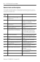
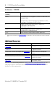
Interpret the LED Indicators
The bicolor (green/red) module status indicator (MODULE) on the front of your module
displays module status. It indicates whether the module has power and is functioning
properly.
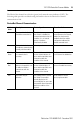
Module Status LED Indicator
Indicator Color Description Corrective Action
Off There is no power applied to the
module.
Verify power connections and apply
power.
Green The module is operating normally. No action required.
Flashing Green The module is not configured. Configure the module.
Flashing Red There is an invalid configuration. Check configuration setup.
Red The module has an unrecoverable
fault.
Replace the module.
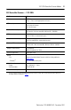
DeviceNet
STATUS
MODULE NET
ADDRESS/ERROR
Module
Numeric
Indicators