Installation Instructions SLC ControlNet Scanner Module Catalog Number 1747-SCNR Use this document to help you install the ControlNet™ 1747-SCNR Scanner module.
SLC ControlNet Scanner Module Important User Information Because of the variety of uses for the products described in this publication, those responsible for the application and use of this control equipment must satisfy themselves that all necessary steps have been taken to assure that each application and use meets all performance and safety requirements, including any applicable laws, regulations, codes and standards.
SLC ControlNet Scanner Module 3 ATTENTION ÿ IMPORTANT Identifies information about practices or circumstances that can lead to personal injury or death, property damage or economic loss. Identifies information that is critical for successful application and understanding of the product.
SLC ControlNet Scanner Module Prevent Electrostatic Discharge The scanner module is sensitive to electrostatic discharge. ATTENTION ÿ Electrostatic discharge can damage integrated circuits or semiconductors if you touch backplane connector pins.
SLC ControlNet Scanner Module 5 Low Voltage Directive This product is tested to meet Council Directive 73/23/EEC Low Voltage by applying the safety requirements of EN 61131-2 Equipment Requirements and Tests. For specific information required by EN 61131-2, see the appropriate sections in this publication as well as the following Allen-Bradley publications: • Industrial Automation Wiring and Grounding Guidelines, publication 1770-4.
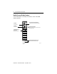
SLC ControlNet Scanner Module Identify Scanner Module Features Use this illustration to identify the features of the 1747-SCNR Scanner module.
SLC ControlNet Scanner Module 7 Prepare for Module Installation Before you install your module, you need the following items: Personal Computer with Microsoft Windows RSNetWorx for ControlNet, catalog number 9357-CNETL3 1747-SCNR Scanner Module Reference Manual, publication 1747-RM623 (The publication number includes the base number only. The current versions will be listed in the Automation Bookstore and Manuals On line.
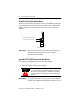
SLC ControlNet Scanner Module Select the ControlNet Node Address Select the ControlNet node address of the 1747-SCNR by setting the two 10-digit rotary switches on the top of the scanner. Valid switch settings range from 01 through 99. Zero (00) is not a valid node address.
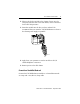
SLC ControlNet Scanner Module 9 2. Select a slot for the module in the chassis. Choose any slot except the left-most slot of the first chassis, which is reserved for the SLC 500 processor. 3. Insert the module into the slot you have selected. We recommend that you insert the 1747-SCNR Scanner as close to the chassis power supply as possible. 30801-M 4. Apply firm, even pressure to seat the module in the I/O chassis backplane connectors. 5. Restore power to the SLC chassis.
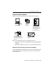
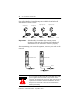
SLC ControlNet Scanner Module Four Allen-Bradley ControlNet taps are available from Rockwell Automation as shown below. Straight T-tap Straight Y-tap 1786-TPS 1786-TPYS Important: Right-angle T-tap Right-angle Y-tap 1786-TPR 1786-TPYR 20094-M Allen-Bradley ControlNet taps contain passive electronics and must be purchased from Rockwell Automation for the network to function properly. After terminating your network segments, connect your node to the network.
SLC ControlNet Scanner Module 11 Remove the tap’s dust cap—located on the straight or right-angle connector—and set it aside. If your network supports Connect the tap’s straight or right-angle connector nonredundant media to the channel A connector on the scanner—channel B is not used.1 from trunk-cable A to channel A on the scanner and from trunk-cable B to channel B on the scanner. redundant media 1. Rockwell Automation recommends using channel A for nonredundant media.
SLC ControlNet Scanner Module Cables Several types of RG-6 quad-shield cables may be appropriate for your ControlNet installation—depending on the environment factors associated with your application and installation site. The following Allen-Bradley ControlNet cable system components are available from Rockwell Automation: Cat. No.
SLC ControlNet Scanner Module 13 Apply Chassis Power Node Address and Status Display 30750-M When you apply chassis power, the module address and status display cycles through the following displays: 1. POST - The 1747-SCNR runs Power On Self Test. 2. 1111, 2222, etc. - The 1747-SCNR is executing its startup sequence. 3. The 1747-SCNR firmware version is displayed temporarily after startup. 4.
SLC ControlNet Scanner Module OK Indicator and Display Mnemonics The OK indicator is handled consistently with the ControlNet specifications for the Identity object. Sequence OK Indicator Startup Run time Alpanumeric Module Status Description Display Word (M1 file) Probable Cause Recommended Action Alternately POST red/ green N/A The 1747-SCNR module is running Power On Self Test. FIRM WARE N/A 1747-SCNR Power was No action firmware applied to the required. revision. This is module.
SLC ControlNet Scanner Module 15 Sequence OK Indicator Alpanumeric Module Status Description Display Word (M1 file) Probable Cause Recommended Action Run time EDIT Edits have been enabled with RSNetWorx for ControlNet. Finish modifying the scanlist with RSNetWorx for ControlNet and then accept edits. Green N/A The scanlist in the 1747-SCNR is being modified. Note: Previously configured connections will be reestablished if lost.
SLC ControlNet Scanner Module Sequence OK Indicator Alpanumeric Module Status Description Display Word (M1 file) Run time I/O 0x22 Connections are configured but no connections are established. I/O 0x23 Connections are configured but only 25% are successfully established. Flashing Green I/O 0x24 50% I/O 0x25 75% Probable Cause Recommended Action View the Connection Status screen in RSNetWorx for ControlNet to see why the connections are not established.
SLC ControlNet Scanner Module 17 Sequence OK Indicator Alpanumeric Module Status Description Display Word (M1 file) Probable Cause Recommended Action Run time EDIT Edits have been enabled with RSNetWorx for ControlNet. Finish modifying the scanlist with RSNetWorx for ControlNet and then accept edits. Flashing Green N/A The scanlist in the 1747-SCNR is being modified. Note: Previously configured connections will be reestablished if lost.
SLC ControlNet Scanner Module Sequence OK Indicator Alpanumeric Module Status Description Display Word (M1 file) Errors Off None N/A Module is not Power supply Check power communicating fault. supply, cable connectors, and seat module firmly in chassis. Flashing Green N/A 0x43 Network error Cable error or Verify network no other cabling. nodes on the network. Red (Scrolling N/A display showing fault details) Module faulted Internal error detected.
SLC ControlNet Scanner Module 19 Status Indicators The ControlNet status indicators inform you of the operational state of the ControlNet network.
SLC ControlNet Scanner Module Specifications SLC ControlNet Scanner Module - 1747-SCNR Module Location Module Defaults Maximum Backplane Current Isolation Voltage Environmental Conditions: Operational Temperature Storage Temperature Relative Humidity Shock unpackaged Vibration Unpackaged Immunity Radiated Fields Agency Certification (when product or packaging is marked) Reference Manual Slot 1 or above Node Address -00 900 mA @ 5V dc Optical Isolation between backplane and ControlNet channel 1 Megoh
SLC ControlNet Scanner Module 21 Hazardous Location Approval The following information applies only to products marked with Hazardous Location Approval, when operating in hazardous locations: Products marked “CL I, DIV 2, GP A, B, C, D” are suitable for use in Class I Division 2 Groups A, B, C, D, Hazardous Locations and nonhazardous locations only. Each product is supplied with markings on the rating nameplate indicating the hazardous location temperature code.
SLC ControlNet Scanner Module Les informations suivantes ne concernent que les produits marqués pour une utilisation en environnements dangereux : Les produits marqués « CL I, DIV 2, GP A, B, C, D » ne conviennent qu’à une utilisation en environnements de Classe I Division 2 Groupes A, B, C, D dangereux et non dangereux. Chaque produit est livré avec des marquages sur sa plaque d’identification qui indiquent le code de température pour les environnements dangereux.
SLC ControlNet Scanner Module 23 Notes: Publication 1747-IN059C-EN-P - September 2001
Allen-Bradley is a registered trademark of Rockwell Automation. SLC is a trademark of Rockwell Automation. ControlNet is a trademark of ControlNet International. Microsoft Windows is a registered trademark of Microsoft Corporation. RSNetWorx for ControlNet and RSLogix 500 are trademarks of Rockwell Software, Inc. CSA logo is a registered trademark of the Canadian Standards Association. Le sigle CSA est la marque déposée de l'Association des Standards pour le Canada.