
Reference Manual User Manual

1 Publication 1747-RM623D-EN-P - June 2006
Chapter
1
Install and Connect the
ControlNet Scanner
What This Chapter Contains
This chapter describes how to install and connect your ControlNet
1747-SCNR scanner. See the table that shows where to find specific
information in this chapter.
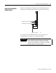
Identify Scanner
Module Features
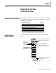
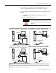
The following drawing identifies the features of the 1747-SCNR
scanner.
For Information About See Page
Identifying scanner features 1-1
Preparing the module for installation 1-2
Selecting the ControlNet node address 1-3
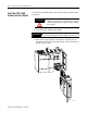
Inserting the 1747-SCNR into an SLC chassis 1-4
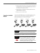
Connecting the 1747-SCNR to a ControlNet network 1-5
SLC 500 I/O configuration 1-8
Node Address and Status Display
displays scanner node address and
status.
Module Status Indicator
indicates whether the device is
powered and is functioning properly.
Channel B
Status Indicator
Channel A
Status Indicator
ControlNet Network
Access Port
NAP RJ45 connector
ControlNet Redundant Media Ports
BNC Connectors
(Channels A and B)
30751