ALLEN–BRADLEY The Getting Started Guide for HHT (Catalog Number 1747–PTA1E & 1747–PT1) User Manual
Important User Information Solid state equipment has operational characteristics differing from those of electromechanical equipment. “Safety Guidelines for the Application, Installation and Maintenance of Solid State Controls” (Publication SGI-1.1) describes some important differences between solid state equipment and hard–wired electromechanical devices.
Preface Preface Read this preface to familiarize yourself with the rest of the manual. This preface covers the following topics: • who should use this manual • the purpose of this manual • how to use this manual • conventions used in this manual • Allen–Bradley support Who Should Use this Manual Use this manual if you are responsible for designing, installing, programming, or troubleshooting control systems that use Allen–Bradley small logic controllers.
Preface Contents of this Manual Chapter: Title: Purpose: 1 Setting Up Your Equipment Shows you how to set up a controller, install your Memory Pak, Battery, and communication cable, and connect your HHT to the controller. 2 Control Basics Presents basic information you will need to know before you can begin programming with the HHT. 3 Creating a Program Shows you how to create a program.
Preface How to Use this Manual To use this manual effectively: • Work through the chapters in sequential order, completing each one before moving on to the next. • Perform the exercises in appendix A to apply what you have learned in the chapters. • Consult appendix B to correct and identify any errors you encounter while working through this manual. • Refer to the glossary for definitions of unfamiliar terms. • Use the index to locate further information on topics.
Table of Contents The Getting Started Guide for HHT Setting Up Your Equipment Chapter 1 Controller Styles . . . . . . . . . . . . . . . . . . . . . . . . . . . . . . . . . . . . . . . . . . . . Setting Up a Demo Unit . . . . . . . . . . . . . . . . . . . . . . . . . . . . . . . . . . . . . . . Setting Up a Field–Wired Controller . . . . . . . . . . . . . . . . . . . . . . . . . . . . . . . Installing the Memory Pak, Battery, and Communication Cable . . . . . . . . . . . HHT Features . . . . . . . . . . .
Table of Contents The Getting Started Guide for HHT Entering an “Examine if Closed” Instruction . . . . . . . . . . . . . . . . . . . . . 3–12 Entering an “Output Energize” Instruction . . . . . . . . . . . . . . . . . . . . . . . 3–13 Saving Your Program . . . . . . . . . . . . . . . . . . . . . . . . . . . . . . . . . . . . . . . 3–14 Online Operations Chapter 4 Downloading Your Program . . . . . . . . . . . . . . . . . . . . . . . . . . . . . . . . . . . . Going Online . . . . . . . . . . . . . . . .
Getting Started Guide for HHT 1 Chapter Chapter 2 A–B Setting Up Your Equipment This chapter briefly describes SLC 500 controller styles, then shows you how to set up your equipment in preparation for the exercises in later chapters.
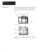
Chapter 1 Setting Up Your Equipment Controller Styles The SLC 500 comes in two different styles: modular and fixed. These styles are shown below. The modular controller consists of a rack, power supply, processor (CPU), and Input/Output (I/O) modules. The fixed controller consists of a power supply, processor (CPU), and a fixed number of I/O contained in a single unit. You can add an expansion rack to the fixed controller.
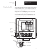
Chapter 1 Setting Up Your Equipment Getting Started Guide for HHT Setting Up a Demo Unit SLC 500 demo units are available with either a fixed controller or modular controller. This guide assumes you are using a modular controller demo unit for all the programming exercises. If you use a fixed controller demo unit, you will need to use different configuration information and I/O addresses in the exercises. This is explained later. The figure below shows an SLC 500 modular controller demo unit.
Chapter 1 Setting Up Your Equipment Setting Up a Field–Wired Controller The details of installing and wiring the controller and external input/output devices are beyond the scope of this guide. If you are using a field–wired fixed or modular controller, refer to the Installation and Operation Manuals, Publication 1747–800 (fixed controllers) and 1747–804 (modular controllers), for information on installation and wiring of the controller and external input/output devices.
Chapter 1 Setting Up Your Equipment Getting Started Guide for HHT B. Insert the memory pak in its compartment as indicated in the following figure. After the memory pak is in the compartment, press down on handle to secure connector in socket. .. . .. .. .. .. .. .. .. .. .. .. ..
Chapter 1 Setting Up Your Equipment 2. Install the battery, catalog number 1747–BA. The battery compartment is next to the memory pak compartment. ! ATTENTION: If you do not install a battery, the letter B appears flashing on the prompt line of the HHT display to let you know that battery power is low; in addition, each time you power up, the self–test diagnostic will be interrupted, and the statement BATTERY TEST FAILED will appear.
Chapter 1 Setting Up Your Equipment Getting Started Guide for HHT 3. Locate the Communications Port of the controller. The figure below shows where it is located on modular and fixed controllers. Processor Module (Modular Controller) (cover open) SLC 500 Fixed Controller (Communication Port) Connectors are keyed. Connect one end of the 1747–C10 communication cable to the top of the HHT.
Chapter 1 Setting Up Your Equipment HHT Features Use the Hand–Held Terminal to configure the SLC 500 controller, enter/modify a user program, download/upload programs, monitor controller operation, test, and troubleshoot. The HHT has its own memory to store a program. You can use the HHT stand alone (for remote programming development with 1747–NP1 or NP2 power supply), point–to–point (one HHT to one controller), or on a DH–485 network (communicate with up to 31 nodes over 4,000 feet).
Chapter 1 Setting Up Your Equipment Getting Started Guide for HHT HHT Powerup After you install the memory pak and battery, and plug in the cable, you can test operation of the HHT by powering up the controller (or plugging in the Wall–Mount or Global Desk Top power supply). When the HHT is energized, it will go through a series of diagnostic tests. Then the following display is shown. SLC 500 PROGRAMMING SOFTWARE Rel. 2.
Chapter 1 Setting Up Your Equipment Data Entry Keys (A 7, B 8, C 9...) These blue keys include numbers, letters, and symbols used for addresses, password, file numbers, and other data. The data you enter always appears on the prompt/data entry/error message area of the display. In general, you obtain the upper character of a key by pressing the [SHIFT] key first. You do not have to hold it and press next key. Just press and release [SHIFT] and then press the next key.
Chapter Getting Started Guide for HHT A–B 2 Control Basics This chapter introduces you to basic concepts essential for understanding how the SLC 500 controller operates. It covers: • SLC 500 file concepts • How external I/O devices communicate with the processor • Addressing external I/O • External I/O addressing formats • Ladder logic concepts SLC 500 File Concepts The CPU, or processor, provides control through the use of a program you create.
Chapter 2 Control Basics Program Files Program files contain controller information, the main control program, and any subroutine programs. The first three program files are required for each program. These are: • File 0 This file stores the controller configuration and other system information. • File 1 This file is reserved for internal controller use. • File 2 This file stores the main control program. • Files 3 – 255 These files are optional and used for subroutine programs.
Chapter 2 Control Basics Getting Started Guide for HHT How External I/O Devices Communicate with the Processor The figure below applies to a modular controller demo unit having an input module in slot 1 and an output module in slot 3. See page 1–2 for a diagram of the slot location. To simplify the illustration, only pushbutton 0 and pilot light 0 of the external I/O are shown. Each of the external input circuits is represented by a status bit in the input data file of the program.
Chapter 2 Control Basics Addressing External I/O As pointed out in the last section, external inputs and outputs are linked to the input data file and output data file of the program. Each status bit in these files has an address. You specify the appropriate address when you enter an instruction in your ladder program.
Chapter 2 Control Basics Getting Started Guide for HHT External I/O Addressing Formats There are three ways in which an external I/O address appears in this guide: • The five keyboard entries you make to enter the address in the HHT: Delimiter Delimiter O:2/7 Output Data File Slot 2 Terminal 7 • The full address, as it appears in the HHT displays: Data File 0 Word 0 O0:2.
Chapter 2 Control Basics Ladder Logic Concepts As we mentioned earlier, the program files you create contain the program used for your controlling application. The programs are written in a programming language called Ladder Logic. This name is derived from its ladder–like appearance. A ladder logic program consists of a number of rungs, on which you place instructions. Instructions each have a data address associated with them and based on the status of these instructions the rung is solved.
Chapter 2 Control Basics Getting Started Guide for HHT Logical Continuity During controller operation, the processor evaluates each rung, changing the status of instructions according to the logical continuity of rungs. More specifically, input instructions set up the conditions under which the processor will make an output instruction true or false.
Chapter 2 Control Basics Processor Operating Cycle The diagram below indicates the events that occur during the processor operating cycle. This sequence is repeated many times each second. Event Description Input Data File Input Scan F8 0 1 address I:1 The status of external input circuits is read. The input data file is updated with this information. data 0001 activated Program Scan I:1.0 ] [ 0 I:1.0 ]/[ 1 Output Data File Output Scan address O:3 The ladder program is executed.
Chapter Getting Started Guide for HHT A–B 3 Creating a Program In this chapter you create a program. The tasks you will perform: • For modular controllers: Make a record of the processor module catalog number, the rack catalog number(s), the I/O module catalog numbers, and the slot locations of I/O modules. For fixed controllers: Make a record of the controller catalog number (and I/O module catalog numbers and slot locations if you are using the 1746–A2 expansion rack).
Chapter 3 Creating a Program Controller Styles As previously mentioned, SLC 500 controllers are available in two styles — the fixed controller and the modular controller. Examples are shown in the figure below. SLC 500 Fixed Controller Processor & Power Supply SLC 500 Modular Controller Expansion Rack 7–slot rack Processor Power Supply Slot 0 1 2 Slot 0 1 2 3 4 5 6 The fixed controller combines a power supply, processor (CPU), and a fixed number of I/O points in a single unit.
Chapter 3 Creating a Program Getting Started Guide for HHT Catalog Number Location – SLC 500 Fixed Controllers Label for Processor Catalog and Serial Number SLC 500 CAT 1747–L _ _ _ Processor Catalog Number The catalog number for the expansion rack is 1746–A2. It appears on side of the rack.
Chapter 3 Creating a Program Arbitrary Controller Used in this Guide In the following procedures, we have assumed that the controller you are configuring in your program is a modular demo unit including the following components: • Rack 1746–A4, 4–slot rack • Processor 1747–L511 in slot 0 • Input module 1746–IA4 in slot 1 • Input module 1746–IA8 in slot 2 • Output module 1746–OA8 in slot 3 The ladder program shown on page 3–11 contains I/O addresses that are consistent with the configuration indicated above
Chapter 3 Creating a Program Getting Started Guide for HHT Clearing the Memory of the HHT To create a new program, you must clear the HHT memory (DEFAULT program). 1. Energize your HHT. After the HHT goes through self–diagnostic tests, the following display appears: SLC 500 PROGRAMMING SOFTWARE Rel. 2.03 1747 – PTA1E Allen–Bradley Company Copyright 1990 All Rights Reserved OFL UTILITY PRESS A FUNCTION KEY SELFTEST TERM PROGMAINT F1 F2 F3 F4 F5 2. Press [F3] – PROGMAINT.
Chapter 3 Creating a Program Naming the Program and Configuring the Controller The following indicates how to name your program and configure your controller using the HHT. Naming Your Program 1. Press [ENTER] to view more options. 2. Press [F1] – CHG_NAM. 3. Press [F2] – PROGRAM. The following display appears: ––––––– Change Program/File Name––––––– File Name: Program Name: DEFAULT ENTER NAME: DEFAULT F1 F2 OFL F3 F4 F5 4. Name your program “1000.” (Press [1][0][0][0][SPACE][ENTER].
Chapter 3 Creating a Program Getting Started Guide for HHT Configuring the Processor 1. Press [ENTER] to view the additional menu functions (as indicated by the > symbol in the lower right corner). The following display appears: File Name: File Name 0 1 2 Prog Name:1000 Type Size(Instr) System * Reserve * Ladder * OFL EDT_DAT SEL_PRO EDT_I/O CLR_MEM F1 F2 F3 F4 > F5 2. Press [F2] – SEL_PRO.
Chapter 3 Creating a Program Configuring Your I/O 1. Press [F3] – EDT I/O. The following display appears: Rack Rack Rack Slot 1 2 3 0 = = = = 1746–A4 NONE NONE 1747–L511 4–SLOT RACK CPU–1K USER MEMORY Slot 1 = NONE MOD_RCK MOD_SLT DEL_SLT UND_SLT F1 F2 F3 F4 F5 The display shows that the processor module we just entered is assigned to slot 0. It also shows the default rack selection 1746–A4. For our example we do not have to change the rack selection.
Chapter 3 Creating a Program Getting Started Guide for HHT 6. Press [F2] – MOD_SLT. 7. Assign 1746–IA8 in slot 2: press the [ ↓ ] key twice, then [ENTER]. The following display appears: Rack Rack Rack Slot 1 2 3 0 = = = = 1746–A4 NONE NONE 1747–L511 Slot 2 = 1746–IA8 4–SLOT RACK CPU–1K USER MEMORY 8–INPUT 100/120 VAC MOD_RCK MOD_SLT DEL_SLT UND_SLT F1 F2 F3 F4 F5 8. Call up slot 3 using the cursor key. Press the [ ↓ ] key once. 9. Press [F2] – MOD_SLT. Slot 3 = NONE appears on the prompt line.
Chapter 3 Creating a Program Monitoring Your Data File To verify that the output and input data files for the I/O modules have been created, you can call up data files for the I/O. 1. Press [F1] – EDT_DAT. The following display appears: Address O0:3.0 15 data 0 0000 0000 8 bits O0:3.0/0 = 0 OFL ADDRESS NEXT_FL PREV_FL NEXT_PG PREV_PG F1 F2 F3 F4 F5 This is file 0, the output data file. It indicates that slot 3 of the controller has 8 bits assigned (representing outputs O:3/0 through O:3/7).
Chapter 3 Creating a Program Getting Started Guide for HHT Programming a Simple Ladder Rung The following rung consists of an XIC input instruction and an OTE output instruction. The addresses conform to the controller configuration indicated in the “Arbitrary Controller” section of this chapter. If you have entered a different controller configuration, make certain that the addresses are consistent with your configuration.
Chapter 3 Creating a Program Entering an “Examine if Closed” Instruction 1. Press [F1] – INS_INST. The following display appears: 2.0.0.0.* BIT OFL TMR/CNT I/O_MSG COMPARE CPT/MTH > F1 F2 F3 F4 F5 2. Press [F1] – BIT. The following display appears: 2.0.0.0.* OFL ] [ ]/[ ( ) (L) (U) F1 F2 F3 F4 F5 > 3. Press [F1] —] [—. The following display appears: ] [ ZOOM on XIC NAME: BIT ADDR: 2.0.0.0.* EXAMINE IF CLOSED Note that the HHT “shifts” for you.
Chapter 3 Creating a Program Getting Started Guide for HHT Entering an “Output Energize” Instruction 1. Press [F3], for the output energize instruction. The following display appears: ZOOM on OTE NAME: BIT ADDR: 2.0.0.0.* ( ) OUTPUT ENERGIZE ENTER BIT ADDR: F1 F2 F3 F4 F5 2. Type bit address O:3/0, then [ENTER]. (If you entered the wrong instruction by mistake, just press [ESC] and try again.) 3. Press [F5] – ACCEPT, then press [ESC] twice. Then press [F5] – ACP_ RNG.
Chapter 3 Creating a Program Saving Your Program Save your program at the end of a program edit. First your program is compiled, transforming it into a more efficient package. Then the program is saved from the work area into another part of memory. In addition, the contents of program files and data files are updated. Also, a summary of data words used, instructions used, and available memory is updated. 1. Start with the screen below, where we left off in the last section. 2.1.0.0.
Chapter Getting Started Guide for HHT A–B 4 Online Operations In this chapter, you will complete the following tasks: • Download program 1000, created in chapter 3. • Test the program. • Monitor the input and output data files.
Chapter 4 Online Operations Downloading Your Program This chapter shows you how to download a program from the HHT to the processor, then monitor the program. It assumes that you have performed the tasks in chapter 3, and that the HHT shows the following display. SLC 500 PROGRAMMING SOFTWARE Rel. 2.03 1747 – PTA1E Allen–Bradley Company Copyright 1990 All Rights Reserved PRESS A FUNCTION KEY SELFTEST TERM PROGMAINT F1 F2 F3 OFL UTILITY F4 F5 Going Online 1. Press [F5] – UTILITY.
Chapter 4 Online Operations Getting Started Guide for HHT Downloading Your Program 1. Press DWNLOAD. The following display appears: Program Directory Programmer Processor Prog: 1000 Prog: DEFAULT File: File: Exec Files: 3 Exec Files: 3 Data Files: 9 Data Files: 3 PRG DOWNLOAD TO PROCESSOR? NO YES F1 F2 F3 F4 F5 2. Press [F2] – YES. This verifies that you want to download the file to the processor. For a brief moment, the following message should appear DOWNLOADING FILE.
Chapter 4 Online Operations 3. Press [F2] – YES. The following display appears again: File Name: File Name 0 1 2 RUN F1 Prog Name:1000 Type Size(Instr) System 76 Reserved 0 Ladder 3 F2 TEST F3 RUN PROGRAM F4 F5 Monitoring the Program in Run Mode 1. Press [ESC], then [ENTER]. The following display appears: File Name: File Name 0 1 2 PASSWRD F1 Prog Name:1000 Type Size(Instr) System 76 Reserved 0 Ladder 3 F2 XFERMEM EDT_DAT F3 F4 RUN MONITOR> F5 2. Press [F5] – MONITOR.
Chapter 4 Online Operations Getting Started Guide for HHT Testing Your Downloaded Program The following diagram shows the rung you entered if you are using the modular controller demo unit discussed in chapter 3. If you are using some other controller configuration, make certain that your external input device and output device are wired to the controller input and output that you addressed in your ladder program. 1 F8 0 0 Address I:1.0/0 corresponds to pushbutton 0 of the demo unit. Address O:3.
Chapter 4 Online Operations 2. Monitor output data changes resulting from input device operation. Press pushbutton 0. Note that the status bit corresponding with output O:3/0 goes from 0 to 1, as the instruction goes from false to true. Address O0:3.0 15 data 0 0000 0001 Bit changes from 0 to 1. O0:3.0/0 = 0 RUN ADDRESS NEXT_FL PREV_FL NEXT_PG PREV_PG F1 F2 F3 F4 F5 3. Press [F2] – NEXT_FL. The following display appears: Address I1:1.0 I1:2.0 15 data 0 0000 0000 0000 I1:1.
Chapter 4 Online Operations Getting Started Guide for HHT 7. Press [F2] – YES. The following screen appears: File Name: File Name 0 1 2 Prog Name:1000 Type Size(Instr) System 76 Reserved 0 Ladder 3 ONLINE WHO PASSWRD F1 F2 F3 OFL CLR_MEM F4 F5 8. Press [ESC]. This brings up the main display.
Chapter 4 Online Operations 4–8
A Appendix Getting Started Guide for HHT A–B Additional Ladder Program Exercises This appendix lets you apply what you have learned in the previous chapters. It covers: • Entering a program with input and output branches • Entering a program with a timer instruction Entering Input and Output Branches The important feature of this program is the output and input branch. The input branch is based on what is called OR or parallel logic.
Appendix A Additional Ladder Program Exercises 4. Press [F2] – MOD_RNG, then [F2] – BRANCH. Adding an Input Branch 5. Press [F4] – INS_BR. Then press the [→] cursor key once, then press [ENTER]. Your new display should look like this: 2.0.1.1.* ( ) ] [ EXT_UP F1 EXT_DWN APP_BR F2 F3 OFL DEL_BR INS_BR F4 F5 Inserting an Instruction 6. Press [ESC], then [F1] – INS_INST, then [F1] – BIT, then [F1] —] [—. 7. Type the bit address I:1/1, then [ENTER]. 8. Then press [F5] – ACCEPT.
Appendix A Additional Ladder Program Exercises Getting Started Guide for HHT Inserting an Instruction 11. Press [ESC] once, then [F1] – INS_INST, then [F1] – BIT, then [F3] —( )—. 12.Type the bit address O:3/1, then [ENTER]. Then press [F5] – ACCEPT. The following display appears: OTE:O0:3.0/1 ] [ ] [ NO FORCE 2.0.1.1.4 ( ) ( ) —] [— —]/[— —( )— F1 F2 F3 —(L)— F4 OFL —(U)— > F5 Saving the Program 13.Press [ESC] twice. Then press [F5] – ACP_RNG. Then press [ENTER]. 14.
Appendix A Additional Ladder Program Exercises 6. Monitor the ladder program and put the processor into the RUN mode. To do this, press [ENTER], then [F5] – MONITOR, then press 2, then [ENTER]. 7. Press [F1] – MODE, then [F1] – RUN, then [F2] – YES, then [ESC]. Testing the Ladder Program 1. Press pushbutton #0. Outputs #0 and #1 turn ON. The following display appears. This input instruction becomes bold. 2.0.0.0.* ] [ ] [ These output instructions become bold.
Appendix A Additional Ladder Program Exercises Getting Started Guide for HHT Entering a Timer Instruction In this exercise, you enter a timer instruction with a time delay of 10 seconds. Two different types of timer status bits activate output pilot lights #0 and #1. The first type, called a “timer timing” status bit turns on output #0 for 10 seconds. The second type, called a “done” status bit, turns on output #1 after 10 seconds.
Appendix A Additional Ladder Program Exercises 3. Enter a rung and an XIC instruction. Press or enter the following: A. [F1] – INS_RNG ] [ B. [F1] – INS_INST C. [F1] – BIT D. [F1] —] [— E. I:1/0 F. [ENTER] G. [F5] – ACCEPT H. [ESC] 4. Enter the Timer Instruction. Press or enter the following: A. [F2] – TMR/CNT ] (TON) [ B. [F1] – TON C. T4:0 (This is the Timer Address.) D. [ENTER] E. 1000 (This is the Timer Preset Value in hundredths of a second.) F. [ENTER] G.
Appendix A Additional Ladder Program Exercises Getting Started Guide for HHT 6. Enter an OTE instruction. Press or enter the following: A. [F3] —( )— ] [ ] [ (TON) B. O:3/0 C. [ENTER] D. [F5] – ACCEPT E. [ESC] F. [ESC] G. [F5] – ACP_RNG 7. Enter a third rung and an XIC instruction. Press or enter the following: ] ] [ [ ] [ (TON) ( ) A. [F1] – INS_RNG B. [F1] – INS_INST C. [F1] – BIT D. [F1] —] [— E. T4:0/13 (13 represents the done bit.) F. [ENTER] G. [F5] – ACCEPT 8.
Appendix A Additional Ladder Program Exercises 9. Save the program. Press or enter the following: A. [ENTER] B. [F5] – SAVE_EX C. [F5] – ACCEPT D. [ESC] 10.Go online and run the program. Press or enter the following: A. [F5] – UTILITY B. [F2] – WHO C. [F3] – ATTACH D. [F4] – MODE E. [F5] – PROGRAM F. [F2] – YES G. [ESC] H. [DWNLOAD] I. [F2] – YES 11. Monitor the ladder program. Press or enter the following: A. [ENTER] B. [F5] – MONITOR C. 2 D. [ENTER] 12.Change Processor Mode to Run.
Appendix A Additional Ladder Program Exercises Getting Started Guide for HHT 13.Test your Ladder Program. Do the following: A. Press pushbutton #0 for at least 10 seconds. During the first 10 seconds, output #0 turns ON and #1 stays OFF. The following display appears: These bit instructions become bold. ] ] ] 2.3.0.0.* (TON) [ [ [ ( ( ) ) RUN MODE FORCE EDT_DAT SEARCH F1 F2 F3 F4 F5 B. After 10 seconds, output #0 turns OFF and output #1 turns ON. The following screen appears: 2.3.0.0.
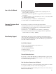
Appendix Getting Started Guide for HHT A–B B Troubleshooting Errors This appendix shows you how to identify and correct errors that you may encounter while working through this guide. They include: • HHT error messages • System LED status • Processor error codes HHT Error Messages The table below details error messages. This Error Message: Appears when: Correct the Error by: Change Processor to Program Mode You attempt to download a program from the HHT to a processor that is in RUN mode.
Appendix B Troubleshooting Errors This Error Message: Appears when: Either you are trying to ATTACH the HHT to either itself or a non–processor device while in the WHO utility. Using the [ ↓ ] or [ ↑ ] keys to change the order of the nodes listed on the WHO screen. Put the processor at the top of the list and try to re–ATTACH. Or you are trying to ATTACH the HHT to a non–existent device, or no devices are shown on the WHO screen.
Appendix B Troubleshooting Errors Getting Started Guide for HHT System LED Status The System LEDs are located at different places on the modular system and the SLC fixed controller. Refer to the Installation and Operation manual for more information on system LED status.
Appendix B Troubleshooting Errors Processor Error Codes The table below details some of the processor error codes. Refer to the HHT manual for a complete list of error codes and troubleshooting information. Error Code Cause Corrective Action RAM program is corrupt due to noise, lightning, improper grounding, or loss of capacitor or battery back–up. Check wiring, layout, and grounding. If using a 4K CPU, verify that a battery is installed to retain RAM memory when power is removed.
Appendix Getting Started Guide for HHT A–B C Identifying HHT Function Keys & Instruction Mnemonics This appendix provides a listing of the abbreviated function keys and their meaning. It also provides a list of instruction mnemonics. HHT Function Keys and Their Meaning Below is a list of abbreviated function keys and their meaning.
Appendix C Identifying HHT Function Keys & Instruction Mnemonics Abbreviation: C–2 Meaning: ENT enter ENT_MAS enter master EXEC_FILE executable files EXT_DWN extend down EXT_UP extend up F force FLT fault INS_BR insert branch INS_INST insert instruction INS_RNG insert rung I/O_MSG I/O message MEM_MAP memory map MEM_PRC memory module to processor MEM_SIZ memory size MOD_INS modify instruction MOD_RCK modify rack MOD_RNG modify rung MOD_SLT modify slot MOR_CPT more com
Appendix C Identifying HHT Function Keys and Instruction Getting Started Guide for HHT Mnemonics Abbreviation: Instruction Mnemonics Meaning: REM_MAS remove master SAVE_CT save and continue SAVE_EX save and exit SEL_PRO select processor SFT/SEQ shift/sequencer SNK sink SRC source SSN single scan TMR/CNT timer/counter TRANS transistor UND_INST undelete instruction UND_RNG undelete rung WTCHDOG watchdog XFERMEM transfer memory The table below provides a complete list of instr
Appendix C Identifying HHT Function Keys & Instruction Mnemonics Mnemonic: C–4 Instruction: GRT greater than HSC high–speed counter IID I/O interrupt disable IIE I/O interrupt enable IIM immediate input with mask INT I/O Interrupt IOM immediate output with mask JMP jump to label JSR jump to subroutine LBL label LEQ less than or equal to LES less than LFL LIFO load LFU LIFO unload LIM limit test MCR master control reset MEQ masked comparison for equal MOV move MUL mul
Appendix C Identifying HHT Function Keys and Instruction Getting Started Guide for HHT Mnemonics Mnemonic: Instruction: SCL scale data SQC sequencer compare SQL sequencer load SQO sequencer output SQR square root STD STI disable STE STI enable STS STI start immediately SUB subtract SUS suspend SVC service communications TND temporary end TOD convert to BCD TOF timer off–delay TON timer on–delay XIC examine if closed XIO examine if open XOR exclusive or C–5
Appendix C Identifying HHT Function Keys & Instruction Mnemonics C–6
Glossary Getting Started Guide for HHT A–B Glossary The following terms are used throughout this manual. Refer to them while working in this manual. address: A character string that uniquely identifies a memory location. For example, I:1/0 is the memory address for the data located in the Input file location 1/0. APS: (Advanced Programming Software) Software for a computer used to monitor and develop SLC 500 ladder logic programs. attach: To establish communication with a processor.
Glossary input device: A device, such as a pushbutton or a switch, that supplies data through input circuits to a programmable controller. input scan: A part of the SLC’s operating cycle. Status of the input modules are loaded into the Input data file. instruction: A mnemonic and data address defining an operation to be performed by the processor. A rung in a program consists of a set of input and output instructions. The input instructions are evaluated by the SLC as being true or false.
Getting Started Guide for HHT Glossary program file: The area within a processor file that contains the ladder logic program. program mode: When the SLC is not executing the processor file and all outputs are de–energized. program scan: A part of the SLC’s operating cycle. During the scan the ladder program is executed and the Output data file is updated based on the program and the Input data file.
Glossary G–4
Index The Getting Started Guide for HHT User Manual A addresses display of, 2–5 formats of, 2–5 specifying, 2–4 input, 2–4 output, 2–4 Allen–Bradley, P–3 contacting for assistance, P–3 auto shift, 1–10 data files, 2–1, 2–2 default types, 2–2 input, 2–2 output, 2–2 timer, 2–2 monitoring, 3–10, 4–5 DEFAULT program, 3–5 demonstration unit components, 3–4 setting up, 1–3 display format, 1–9 displaying addresses, 2–5 B battery, installation, 1–6 Battery Test Failed statement, 1–6 blue keys, 1–10 C catalog nu
Index The Getting Started Guide for HHT User Manual F instructions, inserting, A–2, A–3 false rung conditions, 2–7 features, of HHT, 1–8 field–wired controller, setting up, 1–4 file concepts, 2–1 data files, 2–1, 2–2 processor file, 2–1 program, 2–1 program files, 2–1, 2–2 fixed controller, 1–2 components, 1–2, 3–2 demonstration unit, 1–3 installing and wiring, 1–4 slot numbers, 3–2 function keys, meanings, C–1 FUTACC (Future Access), 3–14 G K keyboard operation, 1–9 auto shift, 1–10 cursor keys, 1–10
Index The Getting Started Guide for HHT User Manual O operating cycle, processor, 2–8 output branch, entering, A–1, A–2 output data file, 2–2 monitoring, 3–10, 4–5 programming a simple ladder rung, 3–11 entering a rung, 3–11 Examine if Closed instruction, 3–12 Output Energize instruction, 3–13 publications, related, P–2, 1–2, 1–4 purple keys, 1–9 Output Energize instruction, 3–13 R P powering up, 1–9 recording, catalog numbers, 3–2 processor operating cycle, 2–8 Run mode changing from Program mode to
A subsidiary of Rockwell International, one of the world’s largest technology companies, Allen-Bradley meets today’s automation challenges with over 85 years of practical plant floor experience. 11,000 employees throughout the world design, manufacture and apply a wide range of control and automation products and supporting services to help our customers continuously improve quality, productivity and time to market.