Installation Instructions Program Storage Device Catalog Number 1747-PSD, Series D Topic Page Important User Information 2 Safety Considerations 3 Environnements dangereux 3 Overview 3 Selector Switch and Pushbutton 5 Battery Compartment 5 LED Indicators 5 User-supplied Power Connection 5 Connect the Program Storage Device 6 Apply Power to the Program Storage Device 7 Use the Program Storage Device 7 Program Transfer Mode between the Program Storage Device and Controller 7 Progra
Program Storage Device Important User Information Solid state equipment has operational characteristics differing from those of electromechanical equipment. Safety Guidelines for the Application, Installation and Maintenance of Solid State Controls (publication SGI-1.1 available from your local Rockwell Automation sales office or online at http://literature.rockwellautomation.com) describes some important differences between solid state equipment and hard-wired electromechanical devices.
Program Storage Device 3 Safety Considerations This equipment is suitable for use in Class I, Division 2, Groups A, B, C, and D, or non-hazardous locations only. The following attention statement applies to use in hazardous locations. WARNING EXPLOSION HAZARD • Substitution of components may impair suitability for Class I, Division 2. • Do not replace components or disconnect equipment unless power has been switched off and the area is known to be non-hazardous.
Program Storage Device The program storage device supports DF1 full-duplex with CRC or BCC error detection, 8 data bits, 1 stop bit, and no parity at communication rates 1200 bps, 2400 bps, 4800 bps, 9600 bps, 19200 bps, and 38400 bps. During operation, the program storage device matches the DF1 communication rate of the SLC or MicroLogix controller. The program storage device will not communicate with a controller if the channel is configured for DH485, DF1 half-duplex or ASCII protocol.
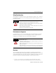
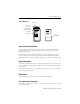
Program Storage Device 5 1747-PSD Features Power Supply Connector Red LED Indicator Green LED Indicator Push Button 7-30 VDC 250mA max RS-232 Port DANGER EXPLOSION HAZARD DO NOT DISCONNECT CONNECTORS OR OPERATE SWITCHES UNLESS AREA IS NON-HAZARDOUS CAT. SER. 1747-PSD Error Complete - OK Linking Executing C FRN. 3 LISTED IND. CONT. EQ. C R US FOR HAZ. LOC. A196 OPERATING TEMPERATURE CODE T3C N223 CLASS I, GROUPS A, B, C, AND D, DIV.
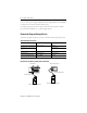
Program Storage Device A 9V dc, Class 2 power supply adapter (120V ac), catalog number 1787-USADPTR, is available for use with the program storage device. The adapter plugs into the power supply connection at the top of the module. For permanent installations, use a power supply adapter. Connect the Program Storage Device Connect the program storage device to the controllers with the appropriate cable.
Program Storage Device 7 Apply Power to the Program Storage Device To apply power, move the selector switch from the OFF/NEXT CMD position to any desired function selection. LED Indicators when Applying Power Red LED Indicator Green LED Indicator Indicates On Off an error at power-up. Flashing Off the program storage device is trying to communicate. Off On the program storage device is able to communicate. Off Off the program storage device is in Sleep mode.
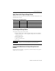
Program Storage Device Program Transfer between the Program Storage Device and Controller Download Industrial Programming Station with RSLogix 500 software, A.I. 500 software, or Advanced Programming Software. Upload To PLC PSD SLC 5/03, 5/04, and 5/05 controller MicroLogix 1000, 1100, 1200, and 1500 controller From PLC Program Transfer between the Program Storage Device and Controller Switch Position Function To PLC Transfers a new program from the program storage device to the controller.
Program Storage Device 9 5. To maximize battery life, slide the selector switch to the OFF/NEXT CMD position. To return the controller to the Remote Run mode following a program transfer, repeat these steps using the mode change command. Incompatibilities When a download from the program storage device is commenced, and the target controller is of an earlier firmware version (Series or OS) than the stored program, the green and red LED indicators flash simultaneously.
Program Storage Device RSLogix 500 software may be used to determine the source of the incompatibility. In Offline mode, set the controller series/revision to that of the target controller and observe the errors indicated by the program verification routine. Refer to Additional Resources for a listing of where you can go to find more information regarding file types, instructions, and controllers.
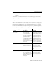
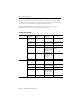
Program Storage Device 11 Incompatible Controllers Controller Controller OS/Series File Types Supported Instructions Supported Comms Supported SLC 5/05 OS501, Series C, FRN 10 and later Security(1) CEM, DEM, RPC, EEM — OS501, Series C, FRN 3...
Program Storage Device Incompatible Controllers Controller Controller OS/Series File Types Supported Instructions Supported MicroLogix 1500 LSP Series C, FRN 6+ Pls, Float(2) CPW, RTA, GCD, ABS, RCP, SCP with FP (FRN 7+) Comms Supported • DF1 Half-duplex Master (FRN 8+) • DF1 Radio Modem (FRN 8+) • Modbus RTU Master (FRN 9+) MicroLogix 1500 LRP Series B, FRN 4...5 String — Modbus RTU Slave Series A, FRN 1...
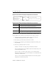
Program Storage Device 13 Program Transfer Mode between the Program Storage Device and Industrial Programming Station Program Transfer mode allows a program to be transferred between the program storage device and the industrial programming station. Program Transfer between the Program Storage Device and Industrial Programming Station Download Industrial Programming Station with RSLogix 500 software, A.I. 500 software, or Advanced Programming Software.
Program Storage Device New program storage device units are loaded with the 5/04 controller identity as default. If the program storage device is to be used with a different controller and the secondary procedure will be used, the desired controller identity must be transferred to the program storage device (using the Program Transfer Mode Controller From PLC command) from the desired controller type (5/03 controller, for example).
Program Storage Device WARNING 15 In all cases, executing a download command will clear the program currently stored in the program storage device. While the command is executing, the green LED indicator flashes. Completion of the transfer is indicated by the programming software package, or by a steadily illuminated LED indicator on the program storage device. Green indicates a successful transfer and red indicates a failed transfer.
Program Storage Device Continue holding the pushbutton until the green LED indicator turns on. 2. Within 10 seconds after the green LED indicator illuminates steadily, release the pushbutton. The green LED indicator turns off. 3. Within 10 seconds, press the pushbutton again. 4. Release the pushbutton within 10 seconds. While the command is executing, the green LED indicator flashes. When execution is complete, either the green or the red LED indicator illuminates steadily for 30 seconds.
Program Storage Device 17 If you want to clear the controller’s memory and the controller is not in Remote Program mode, first follow the Program Transfer Mode - Controller procedure using the mode change command. 1. Hold the pushbutton down and slide the selector switch from OFF/NEXT CMD to mode change to select Clear Memory mode. Continue holding down the pushbutton until the green LED indicator illuminates steadily to indicate program storage device readiness. 2.
Program Storage Device Sleep Mode Sleep mode lets the program storage device conserve battery power by shutting itself off. Following an operation, either the green or the red LED indicator illuminates steadily for 30 seconds before the program storage device enters the Sleep mode. To exit Sleep mode: 1. Turn the switch to OFF/NEXT CMD position. 2. Follow procedure for next command. Interpret the LED Indicators The program storage device has a red and a green LED indicator.
Program Storage Device 19 Troubleshoot the Program Storage Device If an error has occurred, try the following items. • Check the mode of the controller. The controller should be in Remote Program or Remote Run mode. The keyswitch must be in the REM position. • Check the communication cable. • Check the communication parameters. Target settings must be DF1 full-duplex with CRC or BCC, at rates from 1200 to 38400 bps, 8 data bits, 1 stop bit, and no parity.
Certifications Certification(1) Agency Certification (when product or packaging is marked) (1) Value • UL and C-UL Listed • Class I, Division 2, Groups A, B, C, D (with batteries only) • CE/C-Tick compliant for all applicable directives See the Product Certification link at http://ab.com for Declaration of Conformity, certificates, and other certification details. Additional Resources Additional resources related to the Program Storage Device are available.