
Instruction Manual

10 Chassis Interface Module for 1746 Local I/O
Publication 1747-5.32–April 1998
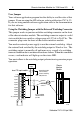
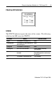
BATT
The BATT indicator reports the health of the battery on the PCI scanner
board. The following table lists the LED states for BATT:
LED 1, LED 2, LED 3, LED 4
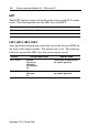
Your application program can control the state of the four user LEDs on
the front of the adapter module. The default state is off. The following
table lists the possible LED states that your program can set.
This state:
Means: Take this action:
Off The battery is OK. None
Red The battery is low or dead. Replace the battery.
This LED:
Can have these states: Take this action:
LED 1 & LED 2 Solid red
Flashing red
Solid green
Flashing green
Off
These actions are determined by
your specific application.
LED 3 & LED 4 Solid red
Solid green
Off
These actions are determined by
your specific application.