Installation Instructions SLC 5/03, SLC 5/04, and SLC 5/05 Modular Processors Catalog Numbers 1747-L531, 1747-L532, 1747-L533, 1747-L541, 1747-L542, 1747-L543, 1747-L551, 1747-L552, 1747-L553 http://literature.rockwellautomation.com/idc/groups/literature/documents/in/1 747-in009_-mu-p.pdf FR Cette publication est disponible en français sous forme électronique (fichier PDF). Pour la télécharger, rendez-vous sur la page Internet indiquée ci-dessus.
Publication 1747-IN009B-EN-P - March 2008
Installation Instructions SLC 5/03, SLC 5/04, and SLC 5/05 Modular Processors Catalog Numbers 1747-L531, 1747-L532, 1747-L533 1747-L541, 1747-L542, 1747-L543, 1747-L551, 1747-L552, 1747-L553 Topic Page Safety Considerations 5 Hazardous Location Considerations 5 Required Tools and Equipment 7 Install the SLC Processor 7 Apply Power to the Processor 8 Loading Your Software 9 Establish Communication to the Processor 9 Replace the Battery 10 Troubleshooting Your SLC Processor 12 Specifica
SLC 5/03, SLC 5/04, and SLC 5/05 Modular Processors Important User Information Solid state equipment has operational characteristics differing from those of electromechanical equipment. Safety Guidelines for the Application, Installation and Maintenance of Solid State Controls (publication SGI-1.1 available from your local Rockwell Automation sales office or online at http://literature.rockwellautomation.
SLC 5/03, SLC 5/04, and SLC 5/05 Modular Processors 5 Safety Considerations ATTENTION Never install, remove, or wire any module while power is applied. Also, do not expose processor modules to surfaces or other areas that may typically hold an electrostatic charge. Electrostatic charges can alter or destroy memory. For general recommendations concerning installation safety requirements and safety related work practices, refer to the requirements specific to your region.
SLC 5/03, SLC 5/04, and SLC 5/05 Modular Processors Environnements dangereux Cet équipement est adapté à une utilisation en environnements de Classe I, Division 2, Groupes A, B, C, D ou dans des environnements non dangereux. La mise en garde suivante porte sur une utilisation en environnement dangereux. AVERTISSEMENT DANGER D'EXPLOSION • La substitution de composants peut rendre cet équipement impropre à une utilisation en environnement de Classe I, Division 2.
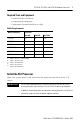
SLC 5/03, SLC 5/04, and SLC 5/05 Modular Processors 7 Required Tools and Equipment • medium blade screwdriver • programming equipment • appropriate network interface or cable Cable Requirements Network Interface Processor SLC 5/03 1747-UIC (1) X SLC 5/04 SLC 5/05 X(4) X(4) X 1747-PIC X 1747-CP3 X X 1784-PKTX(D) X(2) X 1784-PCMK X(3) X(5) 10/100Base-T Ethernet (1) (2) (3) (4) (5) X requires 1747-C13 or 1747-CP3 cable requires 1784-CP14 cable requires 1784-PCM4 cable requires 1747-CP
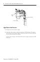
SLC 5/03, SLC 5/04, and SLC 5/05 Modular Processors Power Supply Processor Release Card Guide Protective Wrap Apply Power to the Processor 1. Energize the chassis power supply. 2. Check the chassis power supply and processor LED indicators. The power LED indicator on the power supply should be on and the fault LED indicator on the processor should be flashing. See the figure on page 9 for location of the power supply and processor LED indicators.
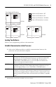
SLC 5/03, SLC 5/04, and SLC 5/05 Modular Processors 9 Power Supply and LED Indicators Indicates the LED indicator is OFF. POWER RUN FORCE FLT DH485 BATT RS232 Indicates the LED indicator is ON. Indicates the LED indicator is FLASHING. Status of LED indicator does not matter. SLC 5/03 POWER RUN FLT BATT FORCE POWER RUN FLT DH+ BATT RS232 FORCE ENET RS232 SLC 5/05 SLC 5/04 Loading Your Software Refer to your programming software documentation. Establish Communication to the Processor 1.
SLC 5/03, SLC 5/04, and SLC 5/05 Modular Processors 2. Set the communication parameters of the software to match the default parameters of the processor. Channel 0 Configuration Channel 1 Configuration SLC 5/03, 5/04, 5/05 SLC 5/03 SLC 5/04 SLC 5/05 DF1 Full-duplex: DH-485: DH+: Ethernet: • no handshaking • 19.2 Kbaud • 19.2 Kbaud • node address = 1 • 57.
SLC 5/03, SLC 5/04, and SLC 5/05 Modular Processors 11 3. Unplug the battery connector. Battery Red White Battery Connector Left Side View IMPORTANT The SLC 5/03, 5/04, and 5/05 processors have a capacitor that provides at least 30 minutes of battery back-up while the battery is disconnected. Data in RAM is not lost if the battery is replaced within 30 minutes. 4. Remove the battery from the retaining clips. 5. Insert a new battery into the battery retaining clips. 6.
SLC 5/03, SLC 5/04, and SLC 5/05 Modular Processors Troubleshooting Your SLC Processor Before troubleshooting your SLC 500 system, please obtain an SLC 500 Modular Hardware Style User Manual, publication 1747-UM011. Refer to the chapter on troubleshooting.
SLC 5/03, SLC 5/04, and SLC 5/05 Modular Processors 13 Specifications Attribute Value Power supply loading at 5V dc 500 mA for the SLC 5/03 processor 1.0 A for the SLC 5/04 and 5/05 processors Power supply loading at 24V dc 175 mA for the SLC 5/03 processor 0 mA for the SLC 5/04 processor (1) 0 mA for the SLC 5/05 processor Program scan hold-up time after loss of power 20 ms...3 s (dependent on power supply loading) Noise immunity NEMA Standard ICS 2-230 Vibration Displacement: 0.015 in.
SLC 5/03, SLC 5/04, and SLC 5/05 Modular Processors Memory Backup The following table shows the memory backup options for the SLC 5/03, 5/04, and 5/05 processors. Flash EPROMs (Flash Erasable Programmable Read Only Memory) combine the versatility of EEPROMs (Electrically-Erasable Programmable Read Only Memory) with the security of UVPROMs (UV-Erasable PROM).
SLC 5/03, SLC 5/04, and SLC 5/05 Modular Processors 15 Shipment of depleted batteries for disposal may be subject to specific regulation of the countries involved or to regulations endorsed by those countries, such as the IATA Restricted Articles Regulations of the International Air Transport Association, Geneva, Switzerland. IMPORTANT Regulations for transportation of lithium batteries are periodically revised. Refer to http://www.dot.gov for the latest shipping information.
Additional Resources Resource Description SLC 500 Modular Hardware Style User Manual, publication 1747-UM011 A more detailed description on how to install and use your modular SLC 500 system. SLC 500 Instruction Set Reference Manual, publication 1747-RM001 A reference manual that contains status file data, instruction set, and troubleshooting information. You can view or download publications at http://literature.rockwellautomation.com.
Notes: Publication 1747-IN009B-EN-P - March 2008
Notes: Publication 1747-IN009B-EN-P - March 2008
Notes: Publication 1747-IN009B-EN-P - March 2008
Rockwell Automation Support Rockwell Automation provides technical information on the Web to assist you in using its products. At http://support.rockwellautomation.com, you can find technical manuals, a knowledge base of FAQs, technical and application notes, sample code and links to software service packs, and a MySupport feature that you can customize to make the best use of these tools.